Sizing relief valves and rupture disks for liquid, choked gas, and flashing two-phase flow using HEM, HDI, and Leung Omega method in SI units.
Peer-Reviewed & PE Verified
ASME VIII • NFPA 68/69 • TEMA • ISO 9001 Alignment
Technical Standard Verified
This technical publication and associated design calculations have been reviewed for engineering consistency, unit integrity, and alignment with standard process design practices (Process Engineering).
Part 3 of 6 in the Technical Series: Emergency Pressure Relief & Effluent Handling Systems
#
Blog 3: Sizing Relief Systems for Single-Phase & Flashing Two-Phase Flows
Accurately determining the required relief device flow area (An) and mass flow rate (W) is fundamental to process safety engineering. While single-phase gas or liquid sizing follows classical fluid mechanics, two-phase flashing flow introduces dynamic phase equilibrium changes, rapid volumetric expansion, and choking at much higher critical pressure ratios.
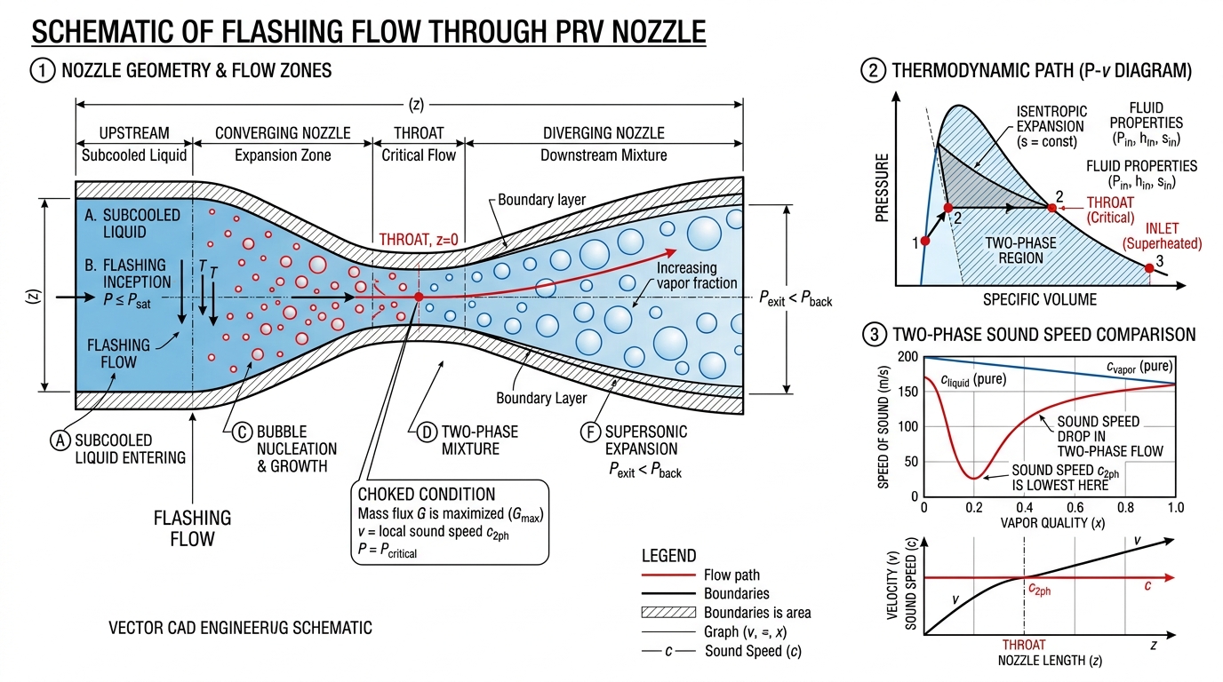
Two-Phase Flashing Flow through Relief Valve Nozzle and Speed of Sound Diagram
#
1. Fundamental Nozzle Flow Model (SI / MKS Units)
The mass flux (Go) through an ideal, frictionless, isentropic relief valve nozzle is calculated by integrating Bernoulli's differential energy balance:
Where:Kv is the viscosity correction factor for NRe<10,000, Kw is the balanced bellows backpressure correction factor, and Pb is backpressure (Pa).
#
B. Compressible Gas / Vapor Flow Sizing (Ideal Gas Choked)
Choked flow occurs when fluid velocity at the nozzle throat reaches sonic velocity (un=c). The critical pressure ratio ηc=Pc/Po is:
When a boiling liquid or two-phase mixture relieves, static pressure drops along the nozzle path. Vapor flashes rapidly, expanding the mixture volume and reducing the speed of sound.
The speed of sound in a homogeneous two-phase mixture (c) drops dramatically below that of pure gas or liquid:
cGc=k1[α(1−α)ρG/ρL]1/2
Example: For a steam-water mixture at void fraction α=0.50, where gas sound speed cG=500 m/s, the two-phase sound speed drops to just 25 m/s! Consequently, two-phase mixtures choke at much higher backpressure ratios (ηc≈0.60−0.85) than pure gases (ηc≈0.53).
Disclaimer: Two-phase relief sizing requires thermodynamic property verification. Use validated simulation tools like SuperChems or CCFlow for detailed design.
Process SafetyRelief Valve SizingTwo-Phase FlowLeung Omega MethodChoked Flow
Comments (0)
Discussion
Please Log In to participate in the technical discussion.
No comments posted yet. Be the first to share your input!