Part 2 of 6 in the Technical Series: Emergency Pressure Relief & Effluent Handling Systems
# Blog 2: Selecting Pressure Relief Devices & Managing Installation Constraints
Selecting the appropriate pressure relief device is a fundamental process safety decision. An improperly selected relief device or poorly designed inlet/outlet piping can trigger violent valve chatter, seat galling, mechanical piping rupture, or loss of containment.
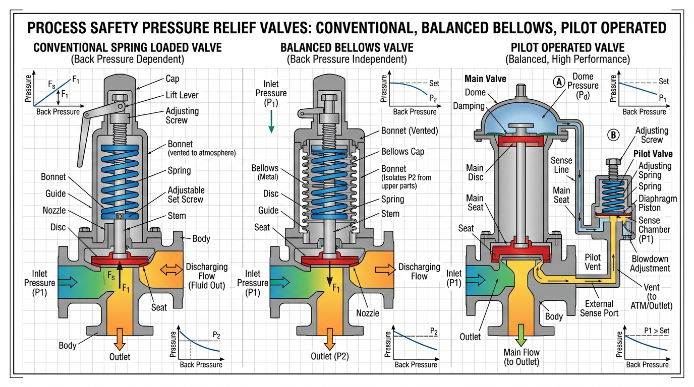
# 1. Primary Types of Pressure Relief Devices
# A. Conventional Direct-Spring Pressure Relief Valves (PRVs)
- Mechanics: A calibrated helical spring exerts a closing force on the disc assembly against nozzle static pressure.
- Backpressure Sensitivity: High sensitivity. Superimposed or built-up backpressure directly adds to the closing force, raising the effective set pressure and reducing flow capacity.
- Application: Services with low, stable backpressure discharging directly to atmosphere or short headers where backpressure stays below of set pressure.
# B. Balanced Bellows PRVs
- Mechanics: Incorporates a metallic bellows with an effective area equal to the seat area, isolating the valve guide, disc holder, and spring from discharge manifold backpressure. The valve bonnet is vented to atmosphere.
- Advantages: Minimizes set pressure variations caused by superimposed or built-up backpressure. Suitable for variable backpressures up to of set pressure.
- Maintenance Caution: Bellows failure converts the valve into a conventional PRV. Superimposed backpressure will then increase the set pressure by an equivalent amount, potentially causing dangerous overpressurization of the upstream vessel.
# C. Pilot-Operated Relief Valves (PORVs)
- Mechanics: Uses a small, self-actuated pilot valve to control gas or liquid pressure in a dome chamber above the main valve piston or diaphragm. System pressure in the dome holds the main valve tightly shut.
- Types:
- Pop-Action Pilot: Opens wide instantly when set pressure is reached.
- Modulating Pilot: Opens proportionally to the required relief load, reducing fluid loss and noise.
- Advantages: Bubble-tight seat seal up to of set pressure; unaffected by high inlet piping pressure drop when equipped with remote pressure sensing.
- Limitations: Unsuitable for dirty, polymerizing, or highly viscous fluids that could plug sensing lines.
# D. Rupture Disk Devices (Non-Reclosing)
- Types: Forward-acting pre-bulged, reverse-buckling scored, and graphite disks.
- Advantages: Leak-tight seal, extremely fast opening speed, lower material cost for exotic alloys, high flow capacity.
- Disadvantages: Remains open after bursting, requiring complete inventory venting unless isolated.
# 2. Key Installation Piping Rules (API 520 / ASME VIII)
graph TD
    Vessel[Protected Vessel P_o] -->|Inlet Friction Loss DP_in <= 3% P_set| PRV[Pressure Relief Valve P_set]
    PRV -->|Built-Up Backpressure P_b <= 10% P_set| Header[Discharge Header / Flare P_atm]
    PRV -.->|If DP_in > 3% P_set| Chatter[VALVE CHATTER & DAMAGE]
    Header -.->|If P_b > 10% P_set| CapacityLoss[CAPACITY LOSS & INSTABILITY]
# The API 3% Rule for Inlet Piping Friction Loss
Excessive friction pressure drop in the piping between the protected vessel and the PRV inlet flange causes severe dynamic instability. When the valve opens, flow commences, generating irreversible pressure losses. If this loss exceeds the valve's blowdown (typically of set pressure), the net force acting on the disc drops below the reseating threshold, forcing the valve shut. Pressure then rebuilds, reopening the valve. This rapid opening and closing cycle—chatter—destroys seating surfaces, causes severe mechanical shock, and can tear piping from vessel nozzles.
Where:
- = Nonrecoverable friction pressure loss ()
- = Total velocity head loss coefficient of inlet pipe, vessel entrance, and fittings
- = Rated mass flow rate at overpressure ()
- = Inlet pipe cross-sectional area ()
- = Relieving fluid density ()
- = Gauge set pressure ()
# 3. DIERS Benchmark Worked Example D.1.2: Heat Exchanger Tube Rupture Scenario
To demonstrate scenario evaluation and device selection under complex multi-phase conditions, consider DIERS Benchmark Example D.1.2 from the book:
# A. Problem Statement & Given Conditions
A vertical thermosyphon reboiler shell side is rated for (). The shell must be protected against a high-pressure tube rupture.
- Tube Conditions: () 16 BWG tubes ( / ), length (). Tubes carry liquid Propane at ().
- Shell Accumulation Limit: For non-fire operating upsets (), the maximum allowable shell relieving pressure is:
- Break Location: Guillotine rupture of one tube occurring () from the bottom tubesheet.
# B. Two-Phase Flow Rate Calculations Through Tube Rupture Ends (TPHEM Code)
Flow occurs simultaneously out of both ends of the severed tube:
- Short-End Break ( length): Subcooled liquid propane enters at (including hydrostatic head) and discharges into the shell at .
- Calculated Flow Rate (): ().
- Long-End Break ( length): Saturated two-phase propane mixture ( vapor quality) flows down through the long tube segment into the shell.
- Calculated Flow Rate (): ().
- Total Rupture Discharge Rate ():
# C. Isenthalpic Flash & Required Relief Capacity
The combined propane stream flashes isenthalpically inside the shell from to the shell relieving pressure of :
- Total Entry Enthalpy: ().
- Liquid Enthalpy at : .
- Vapor Enthalpy at : .
- Flashed Vapor Quality ():
This flashing two-phase mixture ( vapor) displaces shell inventory, establishing the required minimum relief device capacity!
# 4. Combination Devices & Tell-Tale Monitoring
Installing a non-fragmenting rupture disk upstream of a PRV isolates the valve from corrosive, polymerizing, or toxic process media and prevents fugitive emissions.
graph LR
    Vessel[Protected Vessel] --> RD[Non-Fragmenting Rupture Disk]
    RD --> Interspace[Monitored Interspace]
    Interspace --> PRV[Pressure Relief Valve]
    Interspace --> Bleed[Excess Flow Valve / Tell-Tale Gauge & Switch]
    PRV --> Header[Discharge Header / Flare]
# Mandatory Code Rules for Combination Devices (ASME UG-127):
- Combination Capacity Factor (): The certified flow capacity of the PRV alone must be multiplied by a derating factor of unless a higher combination capacity factor is tested and certified under ASME UG-132.
- Interspace Tell-Tale Monitoring: The space between the rupture disk and PRV disc must be continuously monitored and vented using a pressure gauge, try-cock, excess flow valve, or pressure switch alarm. Any pinhole leak or disk seepage will pressurize the interspace, increasing the effective burst pressure of the disk dollar-for-dollar and preventing opening at the design set point!
# 5. Device Comparison Matrix
| Design Parameter | Conventional PRV | Balanced Bellows PRV | Pilot-Operated PRV | Rupture Disk Device |
|---|---|---|---|---|
| Reclosing Capability | Yes | Yes | Yes | No (Stays Open) |
| Max Built-Up Backpressure | of | of | Up to Choked Limit | N/A (Piping Model) |
| Max Operating Margin | of | of | Up to of | of Burst Press. |
| Inlet Loss Sensitivity | High ( Rule) | High ( Rule) | Low (with Remote Sense) | Low |
# ↔️ Series Navigation
- ⬅️ Previous Article: Blog 1: Foundations of Overpressure Protection & International Safety Standards
- ➔ Next Article: Blog 3: Sizing Relief Systems for Single-Phase & Flashing Two-Phase Flows
- 📌 Series Overview & Roadmap: Mastering Pressure Relief & Effluent Handling
Disclaimer: Relief system selection and piping calculations must be verified by a qualified process safety specialist.