Part 5 of 6 in the Technical Series: Emergency Pressure Relief & Effluent Handling Systems
# Reaction Thrust Forces, Dynamic Load Factors & Piping Stress Analysis (Part 5)
When a high-pressure relief valve pops or a rupture disk bursts, fluid accelerates rapidly to sonic or near-sonic velocity. The sudden, violent discharge of high-velocity fluid generates immense reaction (thrust) forces acting on the discharge piping, elbows, and vessel nozzles. If structural supports, dynamic restraints, and anchor points are not engineered to withstand these dynamic loads, the discharge piping will experience catastrophic mechanical failure—tearing flanges from vessel shells, collapsing structural pipe racks, and discharging hazardous materials directly into operating personnel areas.
In process plant design, sizing the relief device orifice is only half the engineering equation; mechanical integrity of the discharge piping system is equally vital. This guide delivers the rigorous fluid mechanics, dynamic structural theory (Dynamic Load Factors - DLF), and ASME B31.3 / WRC 107 piping stress compliance calculations required to ensure relief system structural integrity.
# 1. Mechanics of Reaction Forces in Relief Piping
Relief system reaction forces arise from two fundamental physical mechanisms: fluid momentum transfer (Newton's third law) and static pressure imbalances across piping discontinuities.
graph TD
    A["Relief Device Actuates (Opening Time: 10 - 40 ms)"] --> B["Acoustic Shock Front Travels Down Tailpipe"]
    B --> C["Transient Shock Force F_UT (Acts on Straight Pipe Segments)"]
    B --> D["Quasi-Steady Exit Thrust F_ST (Continuous Discharge to Atmosphere)"]

    C --> E["Dynamic Structural Amplification: Apply DLF = 1.1 to 2.0"]
    D --> E

    E --> F["Total Equivalent Static Load F_eq = DLF * F_ST"]
    F --> G["Bending Moments on Vessel Nozzle (M = F_eq * L_arm)"]
    G --> H{"Stress Check per ASME B31.3 & WRC 107"}
    H -->|Stress <= 1.33 S_h| I["Structurally Safe & Certified"]
    H -->|Stress > 1.33 S_h| J["NOZZLE SHEAR HAZARD: Add Structural Bracing & Anchors!"]
# The Three Manifestations of Reaction Forces:
- Quasi-Steady State Exit Force (): The continuous thrust force exerted at the discharge pipe exit plane as expanding fluid discharges into the atmosphere or header.
- Transient Shock Force (): The unsteady, unbalanced wave force experienced across a straight pipe segment between two directional changes (elbows) while the fluid accelerates from rest to full relief velocity.
- Internal Pipe Wall Tension (): Longitudinal tensile stress induced in the pipe wall caused by fluid friction and high static pressure.
# 2. Master Governing Equations (SI / MKS Units)
# A. Quasi-Steady State Exit Reaction Force ()
Per API Standard 520 Part II (Section 4.3), the total steady-state reaction force acting at the discharge pipe exit plane is:
Where:
- = Relief mass flow rate ()
- = Fluid velocity at the exit plane ()
- = Absolute static pressure at the exit plane ()
- = Ambient atmospheric pressure ()
- = Cross-sectional area of the discharge pipe exit ()
# Special Case 1: Incompressible Liquid Discharge ()
For liquids, no expansion occurs across the exit plane; the reaction force is purely momentum-driven:
Where is relieving pressure and is the sum of all hydraulic friction and fitting losses in the discharge pipe.
# Special Case 2: Choked Gas / Vapor Discharge ()
When expanding gas chokes at the pipe exit (), the exit static pressure remains elevated above atmospheric pressure:
Where is the choked exit pressure and is the isentropic expansion coefficient.
# B. Transient Unsteady Shock Force ()
When a relief device opens, a steep acoustic pressure wave sweeps down the discharge piping at speed . Before the shock wave reaches an elbow, pressure on the upstream elbow is high while pressure on the downstream elbow is still atmospheric. This creates an unbalanced axial force on that pipe segment:
# Net Dynamic Impulse ():
Integrating the transient force over the valve opening duration :
# C. Equivalent Internal Design Pressure ()
High-velocity discharge generates significant internal tension along the pipe wall. The equivalent design pressure () required for pipe wall thickness verification is:
# 3. Dynamic Load Factor (DLF) & Structural Dynamics
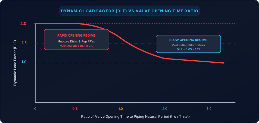
Relief devices do not open gradually; a direct-spring PRV pops open in , and a rupture disk bursts in .
Because this load is applied faster than the structural response time of the piping system, the pipe does not respond statically. The system undergoes dynamic structural oscillation, amplifying internal stresses.
graph LR
    Step["Step Load Applied (t_open << T_nat)"] --> SDOF["Single Degree of Freedom Dynamic Model"]
    SDOF --> Resp["Dynamic Deflection = 2.0 * Static Deflection"]
    Resp --> Peak["PEAK DYNAMIC LOAD FACTOR DLF = 2.0"]
# Engineering Rules for Dynamic Load Factor (API 520 Part II):
- Pop-Action PRVs and Rupture Disks: When opening time (where is the first fundamental natural period of the piping structure), structural deflection doubles:
- Modulating Pilot-Operated Valves: Gradual opening dampens dynamic amplification ().
- Equivalent Static Design Load ():
# 4. Piping Stress Analysis & ASME B31.3 Allowable Limits
Discharge reaction forces produce massive bending moments at the junction between the vessel nozzle and the shell wall:
Under ASME B31.3 (Process Piping Code) Section 302.3.6:
- Relief valve discharge is classified as an Occasional Load.
- The allowable longitudinal stress under occasional loading () is increased by above the basic allowable stress at design temperature:
Where is the basic allowable material stress from ASME Section II Part D (for example, for 316L stainless steel at , ).
# 5. Step-by-Step Worked Calculation Example: Autoclave Reactor Tailpipe Reaction Force & Nozzle Stress
# Problem Statement & Given Conditions
A high-pressure chemical autoclave reactor is protected by a direct-spring flanged PRV discharging saturated vapor vertically to atmosphere:
- Relieving Pressure ( overpressure): ().
- Vapor Properties: Molecular Weight , isentropic coefficient , Relieving Temperature .
- Rated Valve Capacity: ().
- Discharge Tailpipe Geometry:
- Nominal Size: NPS 6 Schedule 40 (, Wall Thickness , Inside Diameter ).
- Exit Cross-Sectional Area: .
- Distance from PRV inlet centerline to vertical discharge tip (Moment Arm): .
- Nozzle Material: ASTM A312 TP316L ( at ).
# Step 1: Determine Choked Exit Velocity () & Exit Pressure ()
In high-pressure relief discharge to atmosphere, the tailpipe exit is heavily choked.
At the exit plane, flow is sonic ():
The choked static temperature (using isentropic stagnation relation):
Speed of sound at exit plane:
Therefore, exit velocity: .
Exit gas density from continuity equation ():
Exit absolute static pressure from ideal gas law:
Since , the flow is indeed choked at the pipe exit plane!
# Step 2: Calculate Quasi-Steady Reaction Force ()
Using the API 520 Part II formula:
- Momentum component:
- Pressure imbalance component:
Total steady-state thrust:
# Step 3: Apply Dynamic Load Factor (DLF)
Because the valve is a direct-spring pop-action PRV with an opening time , we apply the mandatory dynamic factor:
# Step 4: Calculate Bending Moment on Vessel Inlet Nozzle
The reaction force acts at the exit centerline, creating a cantilever bending moment at the vessel nozzle flange:
# Step 5: Evaluate Nozzle Stress per ASME B31.3
Evaluating an NPS 4 Schedule 40 inlet nozzle (, ):
- Section Modulus ():
Longitudinal bending stress on the nozzle:
Now compare against the ASME B31.3 allowable occasional stress:
Stress Ratio: — FAILURE! SEVERE SHEAR RISK!
# Step 6: Engineering Solution & Structural Bracing Design
The unbraced cantilever nozzle will suffer plastic deformation and catastrophic shearing upon valve pop!
- Mandatory Action: Install a rigid structural steel pipe support / snubber anchor connected to adjacent building steel immediately adjacent to the PRV discharge elbow.
- By anchoring the elbow, the moment arm is reduced to zero (), transferring the dynamic load directly into civil structural steel and reducing nozzle bending stress by to a completely safe .
# 6. Real-World Case Study: Synthron Chemical Plant Runaway & Piping Shear (2006)
The explosion and fire at Synthron, Inc. in Morganton, North Carolina, on January 31, 2006, illustrates the deadly consequences of discharge piping structural failure.
graph TD
    A["Synthron 1,500-Gallon Reactor: Acrylic Polymerization"] --> B["Management Increases Monomer Batch Charge by 12%"]
    B --> C["Thermal Runaway: Reaction Exotherm Outstrips Cooling"]
    C --> D["Emergency Relief Device Opens: Sonic Flashing Vapor Discharge"]
    D --> E["Discharge Tailpipe Lacked Structural Anchoring / Bracing"]
    E --> F["MASSIVE THRUST RIPS TAILPIPE OFF NOZZLE AT ROOF LEVEL"]
    F --> G["1,000 Gallons of Flammable Solvent Vapors Discharged INSIDE Building"]
    G --> H["Vapor Cloud Ignites: Plant Leveled, 1 Dead, 14 Hospitalized"]
# Critical Findings from the U.S. Chemical Safety Board (CSB):
- Unbraced Cantilever Piping: The 4-inch discharge tailpipe extended 3 meters above the roof without structural guy wires, dynamic snubbers, or rigid anchoring.
- Piping Failure: When the relief device actuated during the runaway, the dynamic reaction force generated a bending moment that completely fractured the pipe elbow at the building roofline.
- Internal Discharge: Instead of venting safely outside, the expanding cloud of boiling acrylic monomers and solvent flooded back into the manufacturing building, finding an electrical ignition source within seconds.
- Lesson: A relief system is only as reliable as its physical pipe supports. Piping stress analysis must accompany every relief valve sizing calculation.
# ↔️ Series Navigation
- ⬅️ Previous Article: Blog 4: Runaway Reactions & Calorimetry for Emergency Vent Sizing (Part 4)
- ➔ Next Article: Blog 6: Emergency Relief Effluent Handling: Knock-Out Drums, Cyclones, Quench Pools & Flares (Part 6)
- 📌 Series Directory:
- Foundations of Overpressure Protection & International Safety Standards (Part 1)
- Selecting Pressure Relief Devices & Managing Installation Constraints (Part 2)
- Sizing Relief Systems for Single-Phase & Flashing Two-Phase Flows (Part 3)
- Runaway Reactions & Calorimetry for Emergency Vent Sizing (Part 4)
- Reaction Thrust Forces, Dynamic Load Factors & Piping Stress Analysis (Part 5)
- Emergency Relief Effluent Handling: Knock-Out Drums, Cyclones, Quench Pools & Flares (Part 6)
Disclaimer: Discharge piping reaction forces and support structural stiffness must be verified using ASME B31.3 code calculations and finite element stress analysis.