# Relief Valve Sizing: API 520/521 for Process Engineers
Pressure Safety Valves (PSVs) are the final line of defense against catastrophic overpressure in process vessels. If process control loops fail, interlocks bypass, and operator interventions are missed, the PSV must open automatically to discharge vapors and keep the vessel pressure below its maximum allowable working pressure (MAWP).
In this guide, we review the feedback PSV architecture, detail the calculations for Fire Case and Blocked Discharge scenarios in batch reactors using metric units, and walk through real sizing examples.
# 1. Critical Sizing Scenarios (API 521 Guidelines)
To size a relief valve, process engineers must analyze every potential overpressure scenario and select the one that requires the largest discharge area (the governing case):
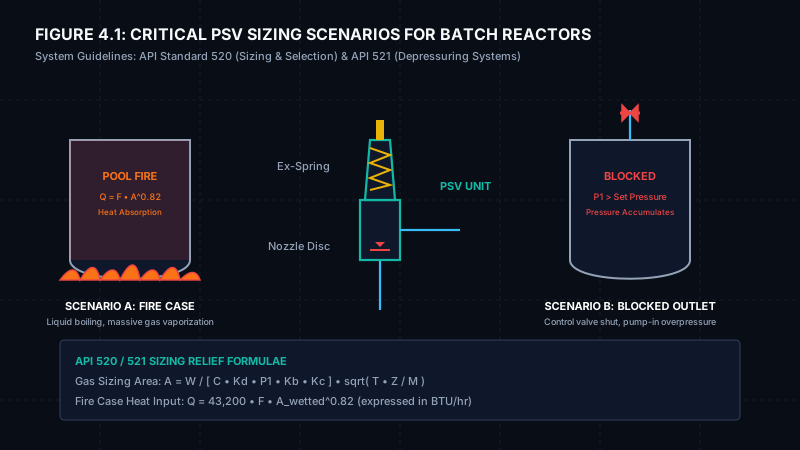
# Scenario A: External Pool Fire Case
- Hazard: An external pool fire surrounds the reactor vessel, heating the liquid solvent inside and causing rapid vaporization.
- Heat Input Calculation (API 521 - Metric System):
Q = 225,900 * F * (A_wetted ^ 0.82)
Where:- Q = Heat absorption rate (expressed in Watts or Joules/sec).
- F = Environment factor (1.0 for bare vessel, 0.3 for insulated vessel, 0.15 for drainage systems).
- A_wetted = Wetted surface area of the vessel exposed to fire (sq meters).
- Relief Load (Vaporization Rate):
W = (Q * 3600) / (lambda * 1000)
Where:- W = Required relief mass flow rate (kg/h).
- lambda = Latent heat of vaporization of the boiling solvent (kJ/kg).
# Scenario B: Blocked Discharge Case
- Hazard: A process control valve on the reactor gas outlet line fails closed, or a manual block valve is closed while reactant feed is pumped in, causing pressure accumulation.
- Relief Load: The relief mass flow rate (W) is equal to the maximum volumetric pumping feed rate (m^3/h) multiplied by the density of the incoming fluid (kg/m^3), yielding flow in kg/h.
# 2. Sizing Calculation Methodology (API 520 Part I - Metric)
For vapor/gas relief under sonic flow conditions, the required orifice area is calculated using the metric formula:
A = W / [ 11.91 * C * Kd * P1 * Kb * Kc ] * sqrt( T * Z / M )
Where:
- A = Required effective discharge area (sq mm).
- W = Required flow rate (kg/h).
- C = Gas expansion coefficient (based on the ratio of specific heats k = Cp/Cv). For typical solvents, C ranges between 315 and 350.
- Kd = Discharge coefficient (typically 0.975 for standard gas PSVs).
- P1 = Relieving pressure (bar a) = Set Pressure + Allowable Accumulation (typically 10% or 21% for fire case) + Atmospheric Pressure (1.013 bar a).
- Kb = Backpressure correction factor (1.0 for conventional valves discharging to atmosphere).
- Kc = Combination correction factor (0.9 if a rupture disk is installed upstream of the valve; otherwise 1.0).
- T = Relieving temperature in Kelvin (K = C + 273.15).
- Z = Compressibility factor (typically 1.0 for low-pressure gases).
- M = Molecular weight of the gas (g/mol).
# 3. Worked Sizing Examples
# Example 1: Fire Case on a Toluene Batch Reactor
- Reactor Details: Insulated jacketed vessel (F = 0.3). Wetted surface area (A_wetted) = 32.5 sq meters.
- Solvent Properties: Molecular weight (M) = 92.14 g/mol. Latent heat of vaporization (lambda) = 360 kJ/kg. Relieving temperature (T) = 110°C = 383.15 K. Specific heat ratio (k) = 1.09 (giving expansion coefficient C = 325).
- Valve Settings: Set Pressure = 3.5 bar g. Accumulation = 21% (fire case limit) = 0.735 bar. Relieving Pressure (P1) = 3.5 + 0.735 + 1.013 = 5.248 bar a.
# Step 1: Calculate Heat Input (Q)
Q = 225,900 * F * (A_wetted ^ 0.82)
Q = 225,900 * 0.3 * (32.5 ^ 0.82) = 67,770 * 17.5 = 1,185,975 Watts = 1,186 kW
# Step 2: Calculate Relief Load (W)
W = (Q * 3600) / (lambda * 1000)
W = (1,185,975 * 3600) / (360 * 1000) = 11,860 kg/h
# Step 3: Calculate Required Orifice Area (A)
A = W / [ 11.91 * C * Kd * P1 * Kb * Kc ] * sqrt( T * Z / M )
A = 11,860 / [ 11.91 * 325 * 0.975 * 5.248 * 1.0 * 1.0 ] * sqrt( 383.15 * 1.0 / 92.14 )
A = ( 11,860 / 19,817 ) * sqrt( 4.158 ) = 0.598 * 2.039 = 1.219 * 1000 = 1,219 sq mm
# Step 4: Orifice Selection
- Comparing 1,219 sq mm against the API 526 table below, a K Orifice (1,186 sq mm) is slightly too small. We select an L Orifice (1,840 sq mm) to provide sufficient relief capacity.
# Example 2: Blocked Discharge Case
- Process Scenario: Toluene feed is pumped into the reactor at a maximum rate of 18 m^3/h (300 L/min). The density of Toluene is 867 kg/m^3. The outlet vapor recovery valve fails closed, compressing the nitrogen blanket gas.
- Gas Properties: Nitrogen gas (M = 28 g/mol, k = 1.4 giving C = 356, T = 20°C = 293.15 K). Relieving Pressure (P1) = 3.5 + 0.35 (10% standard accumulation) + 1.013 = 4.863 bar a.
- Relief Load (W): Peak displacement load is equal to the volumetric inflow weight: W = 18 m^3/h * 867 kg/m^3 = 15,606 kg/h.
# Step 1: Calculate Required Orifice Area (A)
A = 15,606 / [ 11.91 * 356 * 0.975 * 4.863 ] * sqrt( 293.15 * 1.0 / 28 )
A = ( 15,606 / 20,126 ) * sqrt( 10.47 ) = 0.775 * 3.235 = 2.507 * 1000 = 2,507 sq mm
# Step 2: Orifice Selection
- Comparing 2,507 sq mm against the API 526 table below, we select an L Orifice (1,840 sq mm is too small, so we must go to an L Orifice or M Orifice which has an area of 2,322 sq mm. Since 2,507 sq mm is required, we select an N Orifice with an area of 2,800 sq mm).
# 4. API 526 Standard Orifice Letter Designation Table
Once the required relief area (A) is calculated, engineers select the next largest standard orifice size from the chart below:
| Orifice Letter | Area (sq mm) | Area (sq in) |
|---|---|---|
| D | 71 | 0.110 |
| E | 126 | 0.196 |
| F | 198 | 0.307 |
| G | 324 | 0.503 |
| H | 506 | 0.785 |
| J | 830 | 1.287 |
| K | 1186 | 1.838 |
| L | 1840 | 2.853 |
| M | 2322 | 3.600 |
| N | 2800 | 4.340 |
| P | 4116 | 6.380 |
| Q | 7129 | 11.050 |
| R | 10322 | 16.000 |
| T | 16774 | 26.000 |
# 5. Reference Standards Used
- API Standard 520 Part I: Sizing and Selection of Pressure-Relieving Devices.
- API Standard 521: Pressure-relieving and Depressuring Systems.
- API Standard 526: Flanged Steel Pressure-relief Valves.
# 🛠️ Interactive Engineering Tool
To perform calculations related to this topic, access our interactive engineering tool: Emergency Vent Sizing Calculator.
# Applicable Engineering Standards & Codes Used
The engineering methodologies, design correlations, and safety criteria detailed in this article adhere to the following international standards and industry codes:
- OSHA 29 CFR 1910.119: Process Safety Management of Highly Hazardous Chemicals
- NFPA 654: Standard for the Prevention of Fire and Dust Explosions from Combustible Particulate Solids
- NFPA 68: Standard on Explosion Protection by Deflagration Venting
- NFPA 69: Standard on Explosion Prevention Systems
- ACGIH Industrial Ventilation: A Manual of Recommended Practice for Design (30th Edition): ACGIH Industrial Ventilation: A Manual of Recommended Practice for Design (30th Edition)
- ISO 28121: Industrial Ventilation and Dust Collection Systems Safety