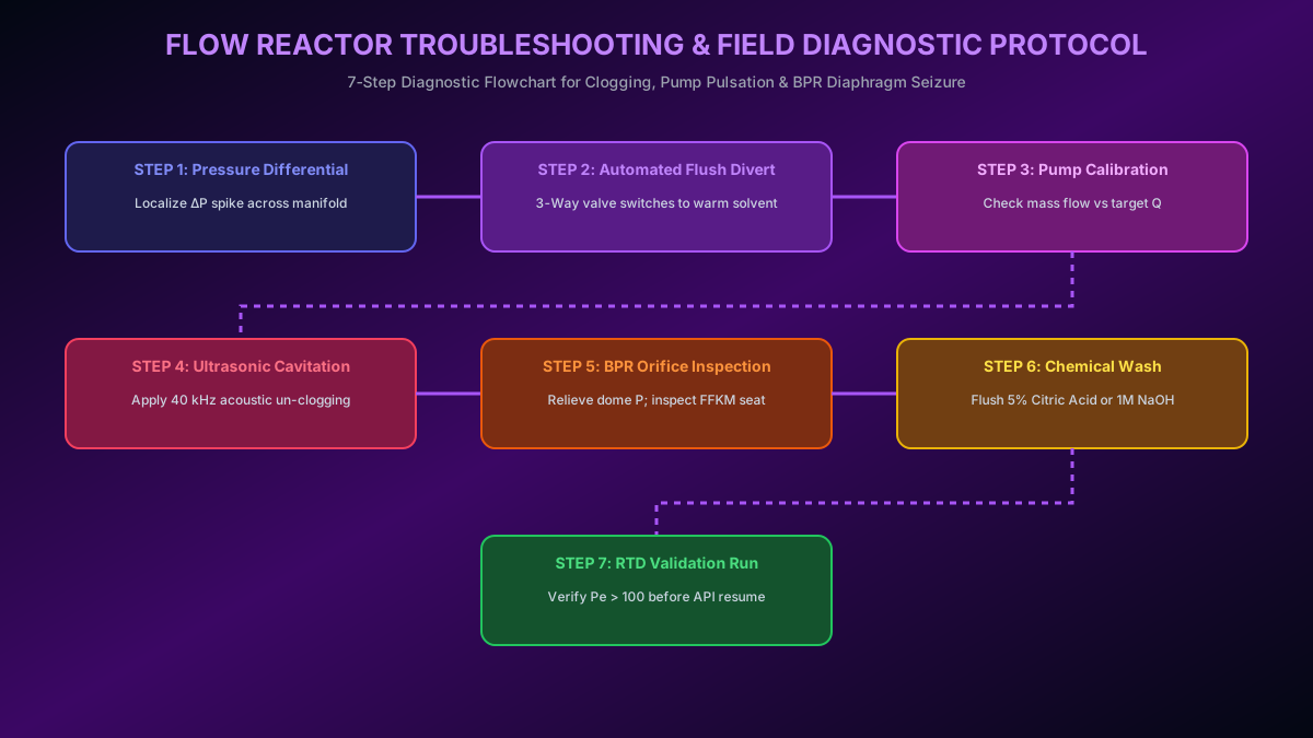
# Industrial Flow Reactor Troubleshooting & Failure Mitigation: Channel Clogging, Pump Pulsation & BPR Seizure
# Executive Summary & Engineering Overview
Continuous flow chemistry skids offer unparalleled thermal control, rapid mixing, and inherently safe operation for active pharmaceutical ingredient (API) synthesis. However, moving from batch vessels to small-bore continuous flow channels () introduces unique hydraulic and mechanical failure modes. Unlike batch reactors where solids can remain suspended by high-power agitators, a continuous flow skid depends on uninterrupted fluid motion.
The three primary failure modes encountered during continuous flow operations are:
- Channel Clogging & Solid Precipitation: Unintended precipitation of inorganic salts, product crystallization, or polymer gumming causing channel constriction and catastrophic pressure spikes ().
- Pump Dosing Pulsation & Cavitation: Flow rate fluctuations () destroying steady-state residence time distribution () or suction check-valve cavitation caused by volatile solvent boiling.
- Back-Pressure Regulator (BPR) Seizure & Chatter: Seating erosion, particulate jamming, or gas-liquid biphasic expansion causing violent pressure oscillations and diaphragm tearing.
This guide provides a comprehensive fluid mechanical diagnostic framework, mathematical models for pressure drop tracking, root-cause failure trees, and automated unclogging protocols for chemical process engineers.
# 1. Physics of Flow Channel Clogging & Solid Deposition
                CONTINUOUS FLOW CHANNEL CONSTRICTION STAGES
 ┌─────────────────────────────────────────────────────────────────────────┐
 │ Stage 1: Clean Channel      Stage 2: Layer Fouling    Stage 3: Clog    │
 │ ┌──────────────────────┐   ┌──────────────────────┐  ┌────────────────┐ │
 │ │                      │   │▒▒▒▒▒▒▒▒▒▒▒▒▒▒▒▒▒▒▒▒▒▒│  │▒▒▒▒▒▒▒▒▒▒▒▒▒▒▒▒│ │
 │ │   Fluid Velocity u   │   │  Constricted Flow    │  │ BLOCKAGE (ΔP↑) │ │
 │ │                      │   │▒▒▒▒▒▒▒▒▒▒▒▒▒▒▒▒▒▒▒▒▒▒│  │▒▒▒▒▒▒▒▒▒▒▒▒▒▒▒▒│ │
 │ └──────────────────────┘   └──────────────────────┘  └────────────────┘ │
 └─────────────────────────────────────────────────────────────────────────┘
# 1.1 Hagen-Poiseuille Hydrodynamics & Constriction Mathematics
Laminar fluid flow through a circular capillary tube of inner diameter and length is governed by the Hagen-Poiseuille Equation:
where:
- is pressure drop across the reactor (),
- is dynamic viscosity (),
- is total channel length (),
- is volumetric flow rate (),
- is hydraulic diameter ().
Notice the inverse fourth-power relationship (). If solid deposition reduces the effective channel diameter by just (), the pressure drop increases by a factor of:
A wall constriction results in a increase in system pressure. If unmonitored, a reduction in channel diameter causes a pressure spike, triggering burst-disk ruptures or pump shutdowns.
# 1.2 Fluid Wall Shear Stress vs. Deposition Rate
Solid particles remain suspended in laminar flow only if the wall shear stress () exceeds the critical adhesion stress () of the crystallizing solute:
If fluid velocity falls below the critical threshold (), the laminar boundary layer velocity approaches zero at the wall (), allowing solute molecules to nucleate, deposit, and form an adherent crystalline layer.
CHANNEL CLOGGING MECHANISMS & CAUSES
┌──────────────────────┬────────────────────────┬────────────────────────┐
│ Clogging Mechanism │ Root Cause │ Affected Reaction Type │
├──────────────────────┼────────────────────────┼────────────────────────┤
│ Inorganic Salt Precip│ Insoluble byproduct │ , Amide Coupling│
│ Product Crystallize │ Low local solubility │ Exothermic Cooling Zone│
│ Polymer / Tar Gumming│ Extended residence time│ Acid-catalyzed Reaction│
│ Quench Precipitation │ Gas evolution / pH drop│ Acid Neutralization │
└──────────────────────┴────────────────────────┴────────────────────────┘
# 2. Real-Time Pressure Derivative Tracking & Automated Diagnostics
# 2.1 The Pressure Derivative Indicator ()
Waiting for absolute system pressure to breach safety limits () is often too late to prevent irreversible clogging. Instead, the automated control skid continuously calculates the first derivative of differential pressure:
                PRESSURE DERIVATIVE CLOGGING DIAGNOSTIC
  Pressure Drop ΔP
   50 bar ┼───────────────────────────────────────────── [ SAFETY TRIP ]
          │                                            /
   30 bar ┼                                          /  (Accelerating Clog)
          │                                 /────────
   10 bar ┼                     /─────────── (PDI Alert Triggered)
    2 bar ┼───────────────────── (Clean Baseline Steady State)
    0 bar ┴─────────────────────────────────────────────► Time (t)
PDI DIAGNOSTIC THRESHOLDS & CONTROL ACTION
┌───────────────────────────┬──────────────────────┬────────────────────────┐
│ PDI Value │ System Status │ Automated Skid Action │
├───────────────────────────┼──────────────────────┼────────────────────────┤
│ │ Normal Steady State │ Continue Operation │
│ │ Early Fouling │ Alert Operator; Temp │
│ │ Active Constriction │ Trigger Auto Solvent Flush│
│ │ Imminent Clog │ Emergency Quench & Divert│
└───────────────────────────┴──────────────────────┴────────────────────────┘
# 3. Active Un-clogging Protocols & Preventative Engineering
# 3.1 Thermal Impulse Dissolution Protocol
Most inorganic and organic crystals exhibit positive temperature dependence on solubility (). When early fouling is detected (), the DCS triggers a Thermal Impulse Cycle:
This temporary temperature boost rapidly increases local saturation concentration , re-dissolving nucleated crystals before they bridge the channel diameter.
# 3.2 High-Pressure Pulsed Solvent Flushing
If thermal impulse is insufficient, a 3-way automated valve switches the reagent feed to an aggressive solvent flush (e.g., DMSO, NMP, or dilute aqueous acid/base):
The threefold increase in flow velocity elevates wall shear stress by , mechanically scouring adhering particles from fluoropolymer or SiC walls.
                 AUTOMATED CLOG MITIGATION WORKFLOW
  [ PDI Monitor ] ──► ( Is PDI > 0.5 bar/min? )
                            │
            ┌───────────────┴───────────────┐
            │ YES                           │ NO
            ▼                               ▼
  [ 1. Activate Auto Flush Valve ]  [ Continue Steady State ]
            │
            ▼
  [ 2. Elevate Thermostat +25°C ]
            │
            ▼
  [ 3. High-Shear Solvent Pulse ]
            │
            ▼
  ( Did ΔP Return to Baseline? )
            │
    ┌───────┴───────┐
    │ YES           │ NO
    ▼               ▼
 [ Resume ]   [ Emergency E-Stop & Back-Flush ]
# 4. Pump Dosing Failures: Pulsation, Cavitation & Check-Valve Malfunction
# 4.1 Check-Valve Ball Seating Failure Mechanics
Reciprocating dual-piston HPLC and diaphragm pumps rely on ruby/sapphire or ceramic ball check valves to enforce unidirectional flow. Micro-particulates or precipitate seeds entering the check-valve housing settle on the toroidal valve seat:
                CHECK-VALVE BALL SEATING FAILURE MECHANISM
 ┌─────────────────────────────────────────────────────────────────────────┐
 │ Normal Seating (Sealed)          Particulate Jamming (Leakage Back)    │
 │      ◯ Ball                             ◯ Ball                         │
 │     /  \                               /  \                            │
 │ ───┴────┴─── Seat                  ───┴──■─┴── Particle Deposit        │
 │   (No Leakage)                       (Back-flow Leakage Q_leak)        │
 └─────────────────────────────────────────────────────────────────────────┘
The resulting back-flow leakage rate () reduces net volumetric dosing efficiency:
# 4.2 Solvent Cavitation & Net Positive Suction Head ()
When pumping volatile solvents at elevated room temperatures (e.g., Dichloromethane , Diethyl Ether ), the static pressure in the pump suction chamber drops below solvent vapor pressure ().
This causes instant solvent vapor bubble formation (cavitation). During the forward stroke, these vapor bubbles collapse violently, resulting in:
- Flow rate collapse (),
- Extreme residence time errors (),
- Piston seal and check-valve erosion.
To prevent cavitation, volatile solvent reservoirs must be chilled to or nitrogen-blanketed to .
# 5. Back-Pressure Regulator (BPR) Seizure & Chatter Diagnostics
# 5.1 Mechanical Spring-Loaded BPR Failure Modes
Spring-loaded needle BPRs utilize a metallic needle held against a seat by a compressed spring.
SPRING-LOADED BPR FAILURE MECHANISMS
┌──────────────────────┬────────────────────────┬────────────────────────┐
│ Failure Mode │ Physical Root Cause │ Operational Symptom │
├──────────────────────┼────────────────────────┼────────────────────────┤
│ Seat Erosion │ High-velocity jetting │ Pressure leakage; │
│ Needle Jamming │ Solid particle wedge │ Pressure lock; │
│ Biphasic Chatter │ Gas expansion resonance│ Violent pressure ripple│
└──────────────────────┴────────────────────────┴────────────────────────┘
When handling gas-evolving continuous reactions (e.g., diazonium Sandmeyer releasing , or decarboxylation releasing ), gas bubbles expand rapidly across the BPR orifice. The compressible gas causes the spring-loaded needle to chatter violently (), destroying pressure stability.
# 5.2 Multi-Diaphragm Dome-Loaded BPR Resolution
Replacing spring-loaded BPRs with Dome-Loaded Multi-Diaphragm BPRs (such as Equilibar regulators) resolves biphasic chatter. The pilot reference gas pressure () acts uniformly across a flexible PTFE/Kalrez diaphragm covering multiple parallel micro-ports.
EQUILIBAR DOME-LOADED BPR HYDRAULIC ADVANTAGE
┌───────────────────────────────────┬───────────────────┬───────────────────┐
│ Metric │ Spring Needle BPR │ Dome-Loaded BPR │
├───────────────────────────────────┼───────────────────┼───────────────────┤
│ Gas-Liquid Biphasic Handling │ Poor (Chatter) │ Excellent (Smooth)│
│ Pressure Control Precision │ │ │
│ Response Time │ │ │
│ Solid Particle Tolerance │ Low (Seat erosion)│ High (Deformable) │
└───────────────────────────────────┴───────────────────┴───────────────────┘
# 6. Master Skid Troubleshooting & Remediation Matrix
COMMERCIAL FLOW SKID DIAGNOSTIC MATRIX
┌──────────────────────┬────────────────────────┬────────────────────────┬────────────────────────┐
│ Observed Symptom │ Probable Failure Mode │ Diagnostic Check │ Remediation Action │
├──────────────────────┼────────────────────────┼────────────────────────┼────────────────────────┤
│ Exponential │ Channel crystallization│ Check PDI ()│ Execute Auto Hot Flush │
│ Cyclic oscillation│ Pump check-valve leak │ Compare flow via balance│ Sonicate/replace check valve│
│ Sudden drop │ BPR diaphragm leak │ Check BPR vent line │ Replace PTFE diaphragm sheet│
│ Volumetric drop │ Suction cavitation │ Check solvent temp/NPSH│ Chill reservoir / Pressurize│
│ Gas buildup in line │ Outgassing / Dissolved │ Inspect inlet lines │ Degas solvents / Increase BPR│
└──────────────────────┴────────────────────────┴────────────────────────┴────────────────────────┘
# 7. Conclusions & Preventative Maintenance Protocols
Achieving high operational availability () in industrial continuous flow API manufacturing requires replacing reactive maintenance with proactive fluid mechanical control:
- Implement Automated PDI Tracking: Use real-time derivative monitoring to trigger solvent flushes before total channel blockage occurs.
- Prevent Cavitation: Maintain by pressurizing or cooling volatile solvent feed tanks.
- Deploy Dome-Loaded BPRs: Use multi-diaphragm BPRs for gas-liquid biphasic or slurry-forming reactions.
- Schedule Ultrasonic Scouring: Utilize continuous inline ultrasonic transducers along capillary reactor tubes to prevent boundary layer crystal nucleation.