# Layer of Protection Analysis (LOPA) & SIL Determination for Exothermic API Reactors: Worked Nitration Case Study
Qualitative hazard identification tools like HAZOP answer the question "What can go wrong?" However, when a HAZOP team identifies a scenario with potential for severe consequences—such as a thermal runaway explosion on an exothermic nitration reactor—qualitative analysis alone is insufficient to answer the critical follow-up question: "Are our existing safeguards adequate, or do we need additional Safety Instrumented Systems (SIS)?"
Layer of Protection Analysis (LOPA) is the semi-quantitative risk assessment methodology used across the pharmaceutical and chemical process industries to evaluate scenario frequency, assess safeguard independence, and calculate required Safety Integrity Levels (SIL 1 to SIL 4) per IEC 61511 / ISA 84.
This guide presents the mathematical foundations of LOPA, the 7 criteria for an Independent Protection Layer (IPL), voting math (1oo2 vs 2oo3), and a fully worked quantitative LOPA case study for a commercial aromatic nitration reactor.
# 1. Mathematical Foundations of LOPA
LOPA calculates the mitigated frequency () of an unwanted consequence scenario by multiplying the Initiating Event Frequency (), Enabler Conditions (), Conditional Modifiers (), and the Probability of Failure on Demand () of each Independent Protection Layer ():
+----------------------------------------------------------------------------+
|                        LOPA RISK CALCULATION CHAIN                         |
|                                                                            |
| [ Initiating Event Frequency f_I ] ---> [ Enabling Conditions P_E ]         |
|                                                  |                         |
| [ Mitigated Frequency f_C ] <--- [ IPL 1..N (PFD_1 x PFD_2 x PFD_N) ] <----+
+----------------------------------------------------------------------------+
# 1.1 Risk Reduction Factor () & SIL Assignment
The Risk Reduction Factor () defines the required risk reduction from a Safety Instrumented Function ():
| Safety Integrity Level (SIL) | Probability of Failure on Demand () | Risk Reduction Factor () | Typical API Plant Application |
|---|---|---|---|
| SIL 1 | () | High-temperature alarm trip; cooling pump start | |
| SIL 2 | () | Exothermic reactor feed trip; automated quench dump | |
| SIL 3 | () | Nitration runaway emergency trip; toxic phosgene shutoff | |
| SIL 4 | () | Nuclear / Extreme Petrochemical (rarely used in API) |
# 2. PFDavg Voting Math for Safety Instrumented Systems
Safety instrumented architectures employ voting logic (1oo1, 1oo2, 2oo3) to balance safety availability against spurious nuisance trips.
# 2.1 1oo1 Architecture (Single Sensor & Valve)
# 2.2 1oo2 Architecture (Redundant Parallel Sensors)
Incorporates Common Cause Failure (-factor):
Where:
- = Dangerous Undetected failure rate ()
- = Proof-test interval (, e.g., 8,760 hrs = 1 year)
- = Common cause failure fraction (typically )
# 3. The 7 Core Criteria for an Independent Protection Layer (IPL)
To qualify as a valid IPL in a LOPA worksheet, a safeguard must satisfy all 7 criteria:
- Specificity: Designed specifically to prevent or mitigate the target scenario.
- Independence: Completely independent of the initiating event and independent of all other IPLs in the scenario (no shared power, shared impulse lines, or common sensors).
- Dependability: Documented, verifiable supported by industry failure rate databases (exIDA, OREDA).
- Auditability: Tested periodically with records maintained under a formal Mechanical Integrity program.
- Access Control: Protected against unauthorized bypass or setpoint modification (password-protected SIS logic).
- Time to Respond: Response time () is significantly less than the time to runaway ().
- Capacity: Sized to handle the maximum credible emergency load (e.g., relief valve sized per DIERS).
# 4. Worked LOPA Case Study: Exothermic Aromatic Nitration Reactor
# 4.1 Scenario Description & Chemistry
- Vessel: 3,000 L Glass-Lined Reactor ().
- Reaction: Nitration of an aromatic API intermediate using mixed acid () at :
- Initiating Event: Cooling Water Pump Failure (Loss of Jacket Cooling).
- Hazard Consequence: Thermal runaway, boiling, gas evolution, vessel rupture, and offsite toxic/fire explosion.
- Tolerable Risk Target (): (Catastrophic Event Target).
                  [ 3,000 L Nitration Reactor R-101 ]
                                   |
         +-------------------------+-------------------------+
         |                                                   |
[ Mixed Acid Feed Line ]                            [ Cooling Water Supply ]
(SIL-2 Feed Isolation Valve)                        (CW Pump Trip = Initiating Event)
# 4.2 Comprehensive LOPA Worksheet
| Step | LOPA Element | Description / Basis | Quantitative Value | Cumulative Frequency () |
|---|---|---|---|---|
| 1 | Initiating Event () | CW Supply Pump Electrical/Mechanical Trip | ||
| 2 | Enabling Condition () | Reaction operated in exothermic regime ( time) | ||
| 3 | Conditional Modifier () | Probability of ignition / explosion upon rupture | ||
| IPL 1 | BPCS High Temp Alarm | High alarm alerts operator to trip feed valve () | ||
| IPL 2 | SIS High-High Temp Trip | SIL-2 1oo2 temp sensors trip automated mixed acid shutoff valve | ||
| IPL 3 | Active Quench Injection | Automated injection of cold water/diluent to arrest exotherm |
# 4.3 Risk Evaluation & SIL Verification
- Target Benchmark: .
- Conclusion: Since , the safety design passes LOPA criteria provided that IPL 2 is validated and maintained as a SIL 2 SIF per IEC 61511 with annual proof-testing ().
# 5. Proof-Testing & Partial Stroke Valve Testing ()
To prevent degradation over time, Safety Instrumented Valves () must undergo Partial Stroke Testing ():
+----------------------------------------------------------------------------+
|              PARTIAL STROKE TESTING (PST) PFD IMPACT                       |
|                                                                            |
| Without PST: PFDavg climbs linearly with time --> Exceeds SIL Target       |
| With PST (Monthly 15% Valve Move): Resets 70% of DU Failures --> Maintains SIL|
+----------------------------------------------------------------------------+
- PST Coverage: Moving a 6-inch feed isolation valve by during active operation detects sticky stems, packing binding, and actuator spring failure without interrupting process flow.
- Benefit: Monthly PST improves by up to , extending full proof-test intervals from 12 months to 36 months.
# 6. Applicable Engineering Standards & Codes
- IEC 61511 / ISA 84: Functional safety - Safety instrumented systems for the process industry sector.
- CCPS Layer of Protection Analysis: Simplified Process Risk Assessment (AIChE).
- ISO 13849: Safety of machinery - Safety-related parts of control systems.
# Historical Background & Foundation
# Layer of Protection Analysis (LOPA): From Concept to Worksheet
In process safety engineering, qualitative hazard identification tools like HAZOP are excellent at listing potential failure scenarios. However, HAZOP struggles to answer a critical quantitative question: Is the current design safe enough, or do we need to add more safety systems?
Layer of Protection Analysis (LOPA) is a semi-quantitative risk assessment method that fills this gap. It evaluates the frequency of an initiating event, reviews the reliability of independent safety layers, and calculates whether the mitigated event frequency meets the facility's tolerable risk target.
# 1. The Concentric Onion Model of Safety
LOPA represents process safety as concentric rings of defense surrounding the core process hazard. Each ring acts as an Independent Protection Layer (IPL) that must function independently of other layers and the initiating event.
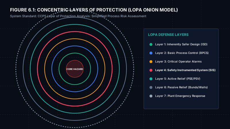
- Core Hazard: The flammable/reactive solvent or pressurized gas system (e.g., hydrogen gas feed).
- Layer 1: Inherently Safer Design (ISD): Minimizing inventory, choosing low-toxicity solvents, or utilizing gravity-drain layouts.
- Layer 2: Basic Process Control (BPCS): Everyday control loops (PID valves, temperature sensors) that keep the process within normal operating envelopes.
- Layer 3: Critical Operator Alarms: DCS alarms that notify operators to intervene manually (such as closing a manual block valve).
- Layer 4: Safety Instrumented System (SIS): Independent safety PLCs that execute automated trips (interlocks) when process variables cross safety thresholds.
- Layer 5: Active Relief Devices: Rupture disks and Pressure Safety Valves (PSVs) designed to discharge excess vapors to safe areas.
- Layer 6: Passive Relief Barriers: Dikes, containment bunds, blast walls, or double-containment piping.
- Layer 7: Plant Emergency Response: Fire suppression systems, evacuation sirens, and community emergency response plans.
# 2. LOPA Safety Mathematics
LOPA calculates risk using the following semi-quantitative terms:
- Initiating Event Frequency (f_i): The expected frequency of the initiating failure (failures/year). For example, a control valve failing open typically has a frequency of 0.1 per year.
- Probability of Failure on Demand (PFD): The probability that a safety barrier will fail to act when called upon. PFD is a dimensionless value between 0 and 1.0 (lower is safer).
- Mitigated Consequence Frequency (f_mitigated): The calculated frequency of the hazardous event after accounting for all active IPLs:
f_mitigated = f_i * PFD_1 * PFD_2 * ... * PFD_n - Tolerable Risk Target (f_target): The maximum acceptable frequency for a specific consequence class. For severe injuries or community fatalities, typical targets range between 1 x 10^-6 and 1 x 10^-5 per year.
- Safety Gap: If f_mitigated is greater than f_target, an engineering gap exists, requiring the installation of additional safety instrumented functions (SIFs) rated for a specific Safety Integrity Level (SIL).
# 3. Case Study: Hydrogenation Loop Reactor Overpressure
# Process Description:
A jacketed loop reactor is used to conduct catalytic hydrogenation of an API intermediate. The reactor operates with a continuous feed of flammable hydrogen gas (H2) at 15 bar g in a methanol solvent. The reactor is rated for a Maximum Allowable Working Pressure (MAWP) of 22 bar g. If the reactor pressure exceeds 22 bar g, it risks catastrophic shell rupture, releasing toxic vapors and initiating a hydrogen gas explosion.
# The Scenario:
The main hydrogen pressure regulator valve fails fully open, bypassing control and dumping high-pressure gas into the reactor. The cooling water jacket pump also trips, leading to temperature and pressure spikes.
# LOPA Sizing Parameters & Data:
- Initiating Event: Pressure regulator control valve fails open (f_i = 0.1 per year).
- Tolerable Risk Target (f_target): 1 x 10^-6 per year (Catastrophic Rupture/Fatality).
- Active Independent Protection Layers (IPLs):
- IPL 1 (BPCS Loop): Reactor pressure transmitter PT-101 detects high pressure and sends a signal to close the H2 flow control valve FCV-101 (PFD = 0.1).
- IPL 2 (Operator Intervention): Independent high pressure alarm (PAH-102) sounds in the control room. The operator has 10 minutes to manually actuate the safety block valve (PFD = 0.1).
- IPL 3 (Safety Instrumented System - SIS): An independent pressure switch (PSH-103) wired to a safety PLC trips close a fast-acting isolation valve (XV-101) on the H2 inlet line. This loop is designed and validated as a SIL-2 function (PFD = 0.01).
- IPL 4 (Active Relief Device): A dual Rupture Disk and PSV set at 20 bar g discharges vapors to a catch tank (PFD = 0.01).
# LOPA Worksheet Segment:
| Column | Description | Value |
|---|---|---|
| Initiating Event | H2 pressure regulator valve fails fully open | f_i = 1.0 x 10^-1 / year |
| IPL 1 (BPCS) | PT-101 closes FCV-101 | PFD = 1.0 x 10^-1 |
| IPL 2 (Operator) | Operator closes manual block valve on alarm | PFD = 1.0 x 10^-1 |
| IPL 3 (SIS / SIF) | SIL-2 High Pressure Trip closes XV-101 | PFD = 1.0 x 10^-2 |
| IPL 4 (Active Relief) | Rupture Disk & PSV open at 20 bar g | PFD = 1.0 x 10^-2 |
| Mitigated Frequency | Calculated frequency of reactor rupture | f_mitigated = 1.0 x 10^-7 / year |
| Tolerable Target | Target safety limit | f_target = 1.0 x 10^-6 / year |
| Safety Gap | Difference between target and mitigated | Zero (Design is compliant) |
# Calculation Analysis:
f_mitigated = (1.0 x 10^-1) * (1.0 x 10^-1) * (1.0 x 10^-1) * (1.0 x 10^-2) * (1.0 x 10^-2) = 1.0 x 10^-7 per year
Since the mitigated frequency (1.0 x 10^-7/year) is lower than the tolerable risk target (1.0 x 10^-6/year), the current design is considered safe and compliant under CCPS guidelines. No further safeguards are required.
# 4. Reference Standards Used
- IEC 61511: Functional safety - Safety instrumented systems for the process industry sector.
- CCPS Guidelines for Layer of Protection Analysis: (Center for Chemical Process Safety).
- ISA-84.00.01: Application of Safety Instrumented Systems for the Process Industries.
# Applicable Engineering Standards & Codes Used
The engineering methodologies, design correlations, and safety criteria detailed in this article adhere to the following international standards and industry codes:
- US FDA 21 CFR Part 211: Current Good Manufacturing Practice for Finished Pharmaceuticals
- EU GMP Annex 1: Manufacture of Sterile Medicinal Products
- ISPE Baseline Pharmaceutical Engineering Guide (Vol 1-7: Bulk Active Pharmaceutical Ingredients, Water & Steam Systems): ISPE Baseline Pharmaceutical Engineering Guide (Vol 1-7: Bulk Active Pharmaceutical Ingredients, Water & Steam Systems)
- WHO Technical Report Series No. 961: Supplementary Guidelines on Good Manufacturing Practices for Heating, Ventilation and Air Conditioning