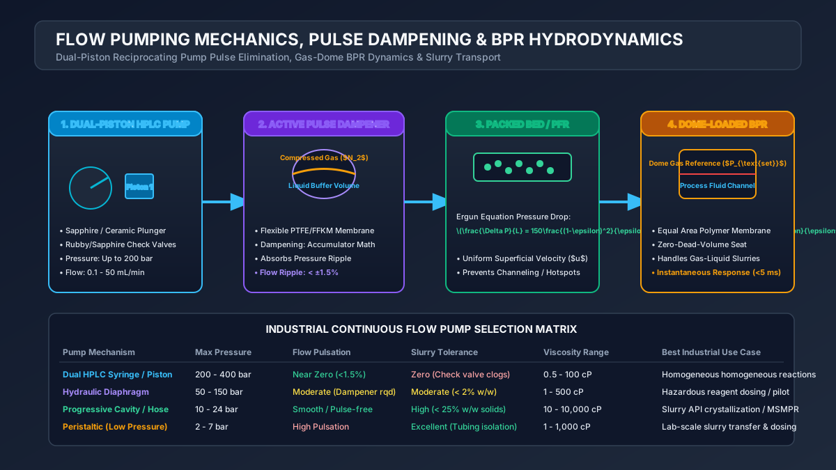
# Flow Pumping Mechanics, Slurry Handling, Pulse Dampener Math & BPR Hydrodynamics in Continuous Skids
# Executive Summary & Engineering Context
In continuous flow chemistry and active pharmaceutical ingredient (API) manufacturing, maintaining precise, non-pulsating flow rates and stable system pressures is essential for process safety, product selectivity, and quality control. Unlike batch processes where liquid movement is largely un-metered bulk transfer, continuous flow skids require dosing accuracy within across system operating pressures ranging from 1 to 200 bar.
Fluid delivery challenges in continuous flow skids center on four critical fluid mechanical phenomena:
- Pump Head Pulsation: Reciprocating positive-displacement pumps generate sinusoidal flow fluctuations, causing transient residence time variations () and destroying steady-state reaction kinetics.
- Slurry Settling & Clogging: Transporting heterogeneous solid-liquid suspensions (e.g., heterogeneous catalysts, inorganic bases like ) through small-bore tubing () risks rapid channel blockage if fluid velocity drops below critical deposition velocity ().
- Back-Pressure Regulation (BPR): Spring-loaded needle BPRs suffer from seat erosion and pressure chatter when handling gas-liquid biphasic streams, requiring multi-diaphragm dome-loaded technology.
- Net Positive Suction Head (NPSH): Volatile solvents (e.g., DCM, THF, diethyl ether) operating near their boiling point can undergo cavitation in the pump inlet head, causing catastrophic volumetric dosing errors.
This masterclass details the fluid mechanical equations, pulse dampener sizing math, slurry transport criteria, and back-pressure regulator hydrodynamics necessary to design robust continuous flow skids.
# 1. Pumping Technology Selection & NPSH Hydrodynamics
# 1.1 Comparative Analysis of Dosing Pumps for Flow Skids
PUMP TECHNOLOGY COMPARATIVE SELECTION MATRIX
┌──────────────────────┬────────────────────────┬────────────────────────┬────────────────────────┐
│ Pump Type │ Max Pressure (bar) │ Flow Pulsation (%) │ Slurry Capability │
├──────────────────────┼────────────────────────┼────────────────────────┼────────────────────────┤
│ Dual-Piston HPLC │ 400 │ (Cam-driven)│ Poor (Check valve clog)│
│ Peristaltic │ 10 │ │ Excellent (No valves) │
│ Hydraulic Diaphragm │ 200 │ │ Moderate (Wetted seats)│
│ Progressive Cavity │ 24 │ (Pulse-free)│ Excellent (High solids)│
│ Syringe Pump │ 100 │ (Pulse-free) │ Fair (Settling in barrel)│
└──────────────────────┴────────────────────────┴────────────────────────┴────────────────────────┘
# 1.2 Net Positive Suction Head () Calculation
To prevent solvent cavitation in the suction check valve, the available Net Positive Suction Head () must exceed the pump's required Net Positive Suction Head () by at least :
where:
- is absolute pressure in the feed tank (),
- is solvent vapor pressure at suction temperature (),
- is solvent density (),
- is acceleration due to gravity (),
- is static suction head (, positive if tank is elevated above pump),
- is friction head loss in suction piping (),
- is acceleration head loss caused by reciprocating piston action ().
# 1.3 Acceleration Head () for Reciprocating Pumps
For a reciprocating piston pump operating at speed (), acceleration head loss in a suction line of length and internal diameter is calculated as:
where:
- is mean fluid velocity (),
- is pump factor ( for duplex double-acting, for simplex single-acting),
- is fluid compressibility factor ( for liquids).
# 2. Pulse Dampener Mathematical Modeling & Sizing
# 2.1 Physics of Reciprocating Flow Pulsation
A single-piston reciprocating pump generates a sinusoidal flow profile:
where is piston cross-sectional area, is crank radius, and is angular velocity ().
The displacement volume per stroke is:
                 UN-DAMPENED VS. DAMPENED FLOW PULSATION
  Flow Rate Q
   1.5 Q_avg ┼─────/\──────/\──────/\───── (Un-dampened Sinusoidal Flow)
   1.0 Q_avg ┼─────────────────────────── (Target Steady State Flow)
   0.5 Q_avg ┼─────\/──────\/──────\/─────
   0.0       ┴─────┬───────┬───────┬─────► Time (t)
# 2.2 Ideal Gas Law Pulse Dampener Sizing Derivation
A gas-charged accumulator (bladder or dome dampener) absorbs fluid volume during the discharge stroke and delivers it back during the suction stroke.
Applying the ideal gas law under isothermal conditions ():
where:
- is pump constant ( for duplex, for triplex),
- is dampener gas pre-charge pressure (, set to ),
- is maximum allowable system pressure (),
- is target residual pulsation percentage ().
PULSE DAMPENER SIZING TABLE FOR A DUPLEX HPLC PUMP
┌───────────────────────────────────┬───────────────────┬───────────────────┐
│ Parameter │ Value │ Engineering Units │
├───────────────────────────────────┼───────────────────┼───────────────────┤
│ Piston Stroke Volume ()│ │ mL / stroke │
│ Operating Flow Rate │ │ mL / min │
│ Operating Pressure ()│ │ bar │
│ Pre-charge Pressure ()│ │ bar () │
│ Target Residual Pulsation ()│ │ 0.02 │
│ Minimum Dampener Volume () │ │ mL │
└───────────────────────────────────┴───────────────────┴───────────────────┘
# 3. Slurry Transport Hydrodynamics in Small-Bore Channels
# 3.1 Critical Deposition Velocity () & Durand Equation
Transporting solid catalyst particles or insoluble inorganic salts (, ) through flow tubing without channel deposition requires maintaining fluid velocity above the Critical Deposition Velocity ().
Using the modified Durand Correlation:
where:
- is Durand factor (dependent on particle size and concentration ),
- is tube inside diameter (),
- is solid particle density (),
- is liquid carrier density ().
                CRITICAL DEPOSITION VELOCITY VS. TUBE DIAMETER
  Critical Velocity v_c (m/s)
   1.5 ┼                                       /  (Un-safe Deposition Zone Below)
   1.0 ┼                             /────────
   0.5 ┼                  /──────────
   0.0 ┴──────────────────┴───────────────────► Tube Inner Diameter D (mm)
       0                  1.5                 3.0
# 3.2 Anti-Clogging Active Mitigation Strategies
- Active Ultrasonic Agitation: Wrapping piezo-electric ultrasonic transducers () along the outer wall of fluoropolymer tubing imparts high-frequency acoustic cavitation, preventing crystal adhesion to channel walls.
- Peristaltic Flow Actuation: Pulsed micro-slug flow creates high wall shear stress (), scouring settling particles.
- Inline Micro-Milling: Installing inline high-shear rotor-stator wet mills upstream of flow reactors reduces particle size .
# 4. Back-Pressure Regulator (BPR) Hydrodynamics
# 4.1 Comparison: Spring-Loaded vs. Dome-Loaded Diaphragm BPRs
BACK-PRESSURE REGULATION COMPARISON
┌──────────────────────┬────────────────────────┬────────────────────────┐
│ Feature │ Spring-Loaded BPR │ Dome-Loaded BPR (Equilibar)│
├──────────────────────┼────────────────────────┼────────────────────────┤
│ Sealing Mechanism │ Spring-pressed needle/ball│ Flexible multi-diaphragm│
│ Biphasic Handling │ Poor (Severe chatter) │ Outstanding (Gas/Liquid)│
│ Pressure Control Range│ │ │
│ Slurry Tolerance │ Poor (Seat erosion) │ High (Soft diaphragm) │
│ Wetted Materials │ SS316, PEEK │ Hastelloy, PTFE, Kalrez│
└──────────────────────┴────────────────────────┴────────────────────────┘
# 4.2 Dome-Loaded Diaphragm BPR Working Principle
A Dome-Loaded Multi-Diaphragm BPR (such as an Equilibar regulator) uses a 1:1 pilot gas reference pressure applied to the top of a thin, flexible diaphragm over a grid of multiple micro-orifice ports.
                 DOME-LOADED MULTI-DIAPHRAGM BPR SCHEMATIC
 ┌─────────────────────────────────────────────────────────────────────────┐
 │                        Pilot Gas Reference (P_pilot)                    │
 │                                    │                                    │
 │                                    ▼                                    │
 │       ┌────────────────────────────────────────────────────────┐        │
 │       │ Flexible PTFE / Kalrez Diaphragm Membrane             │        │
 │       └────────────────────────────────────────────────────────┘        │
 │              ▲                   ▲                   ▲                  │
 │   Fluid In   │                   │                   │     Fluid Out    │
 │  ────────────┴───────────────────┴───────────────────┴──────────────►   │
 │              Port 1              Port 2              Port 3             │
 └─────────────────────────────────────────────────────────────────────────┘
When liquid pressure () slightly exceeds pilot gas pressure (), the diaphragm lifts by a few micrometers, opening a variable flow area. Because the diaphragm mass is negligible (), the response time is instantaneous (), dampening two-phase slug flow expansion without pressure spikes.
# 5. Operational Troubleshooting & Diagnostics
SKID HYDRAULIC TROUBLESHOOTING MATRIX
┌──────────────────────┬────────────────────────┬────────────────────────┐
│ Symptom │ Root Cause │ Corrective Protocol │
├──────────────────────┼────────────────────────┼────────────────────────┤
│ Erratic Flow Rate │ Air bubble in pump head│ Purge with IPA at high flow│
│ Pressure Spike │ Channel clogging │ Reverse flow / Hot solvent flush│
│ BPR Pressure Drift │ Diaphragm tear or debris│ Replace PTFE diaphragm sheet│
│ Pump Cavitation Noise│ Solvent boiling ()│ Elevate tank / Cool inlet line│
└──────────────────────┴────────────────────────┴────────────────────────┘
# 6. Conclusions & Engineering Summary
Designing robust fluid delivery systems for continuous flow skids requires mastering fluid mechanics at small scales. By implementing proper NPSHa calculations, gas-charged pulse dampener math, Durand slurry transport criteria, and dome-loaded BPR technology, chemical engineers ensure steady-state operational stability, uncompromised safety, and exact stoichiometric dosing in commercial API manufacturing.