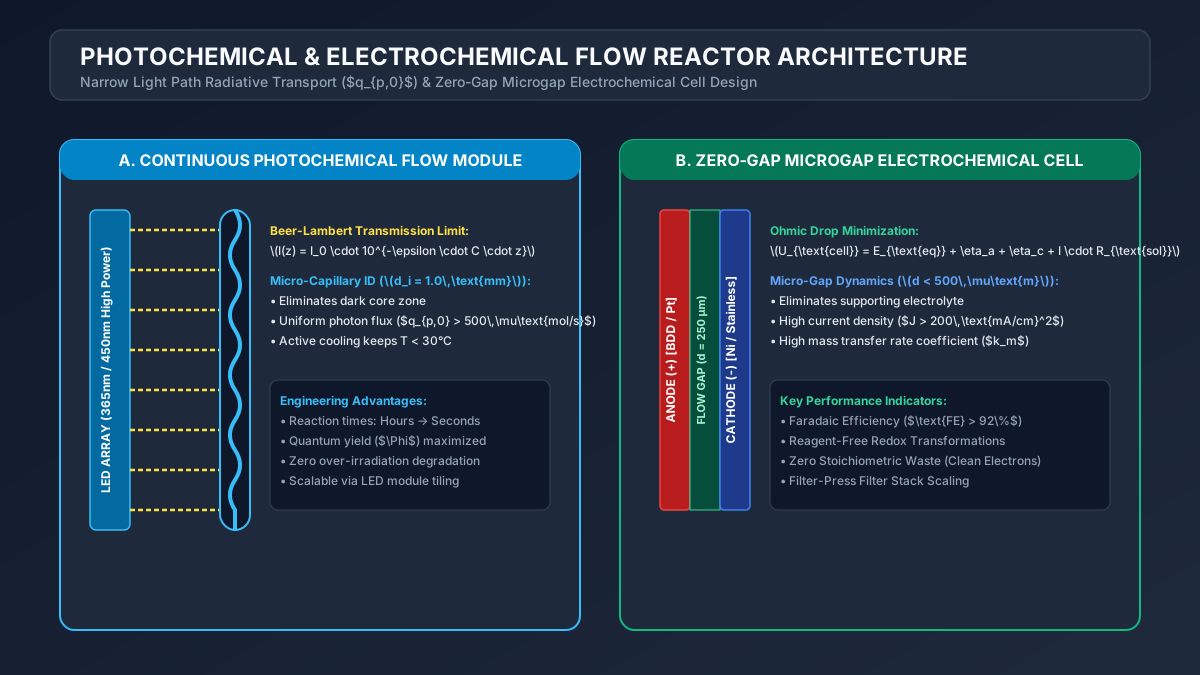
# Photochemical & Electrochemical Flow Reactor Engineering: Radiative Transport, Photon Flux, Zero-Gap MEA Cells & Scale-Up Hydraulics
# Executive Summary & Industrial Relevance
In modern active pharmaceutical ingredient (API) synthesis and green chemistry, Photochemical and Electrochemical transformations offer unparalleled synthetic utility. Photochemistry enables access to high-energy, strained carbocyclic structures ([2+2] cycloadditions, Norrish type reactions) using light as a traceless reagent. Electrosynthesis replaces stoichiometric, hazardous redox reagents (e.g., Chromium VI, , lithium aluminum hydride) with clean electrical current ().
However, scaling these technologies in traditional batch reactors has historically proven nearly impossible:
- Photochemical Batch Failure: Attenuation of light by Beer-Lambert absorption limits effective photon penetration to a few millimeters near the vessel wall.
- Electrochemical Batch Failure: Massive ohmic voltage drop across wide inter-electrode gaps () causes severe resistive heating ( losses), poor current distribution, and low Faradaic efficiency.
Continuous Flow Photochemical and Electrochemical Reactors solve these physical limitations. Micro/meso-fluidic flow channels () provide uniform photon penetration and zero-gap membrane electrode assemblies (MEA), enabling predictable, highly efficient, and scalable manufacturing.
This guide details the radiative transport physics, electrochemical kinetics, cell fluid dynamics, and scale-up hydraulics required to design commercial photo- and electro-flow reactors.
# 1. Photochemical Flow Reactor Engineering
# 1.1 Radiative Transport & Beer-Lambert Law
The spatial distribution of light intensity inside a photochemical flow channel is governed by the Radiative Transfer Equation (RTE). For non-scattering homogeneous liquid media, this simplifies to the unidimensional Beer-Lambert Law:
where:
- is the incident photon flux density ( or ),
- is the molar decadic absorption coefficient (),
- is the concentration of absorbing chromophore (),
- is the depth from the illuminated reactor wall ().
                     BEER-LAMBERT LIGHT INTENSITY ATTENUATION
  Light Intensity I(z) / I0
   1.0 ┼───────┐
   0.8 ┤       │\
   0.6 ┤       │ \  Exponential Decay: I(z) = I0 * 10^(-ε C z)
   0.4 ┤       │  \
   0.2 ┤       │   └───┐
   0.0 ┴───────┴───────┴─────────────────────────────► Depth z (mm)
       0      0.5     1.0                           1,000 (Batch Vessel)
               ▲
               │ Microfluidic Flow Channel Path Length (z <= 1.0 mm)
# 1.2 Optimal Channel Path Length () & Quantum Yield ()
If the flow channel diameter is too large (), the core of the channel remains dark (un-irradiated zone). Conversely, if is too small (), a significant fraction of photons pass unabsorbed through the channel (light waste).
The Optimal Optical Path Length () for photon absorption () is derived as:
OPTIMAL PATH LENGTH FOR COMMON CHROMOPHORES
┌──────────────────────┬────────────────────────┬────────────────────────┬────────────────────────┐
│ Chromophore / Catalyst│ Molar Absorbance ()│ Concentration () │ Optimal Path ()│
├──────────────────────┼────────────────────────┼────────────────────────┼────────────────────────┤
│ │ ()│ │ │
│ │ () │ │ │
│ Benzophenone │ () │ │ │
│ Enone ([2+2] Substrate)│ () │ │ │
└──────────────────────┴────────────────────────┴────────────────────────┴────────────────────────┘
The overall Photochemical Quantum Yield () is defined as:
# 1.3 LED Light Source Selection & Glass Transmittance
The choice of window material and LED wavelength () dictates energy efficiency:
WAVELENGTH TRANSMITTANCE & GLASS SELECTION
┌──────────────────────┬────────────────────────┬────────────────────────┐
│ Glass Material │ Cut-off Wavelength │ Typical Applications │
├──────────────────────┼────────────────────────┼────────────────────────┤
│ Synthetic Quartz │ │ Deep UV (UVC: 254 nm) │
│ High-Purity FEP │ │ UVB / UVA (300–400 nm) │
│ Borosilicate 3.3 │ │ UVA / Visible Light │
│ Soda-Lime Glass │ │ Visible Light (>400 nm)│
└──────────────────────┴────────────────────────┴────────────────────────┘
# 2. Electrochemical Flow Reactor Engineering
# 2.1 Zero-Gap Membrane Electrode Assembly (MEA) Architecture
In continuous electrosynthesis, traditional divided cells with wide gaps () cause high electrical resistance (). The Zero-Gap MEA Cell Architecture presses porous gas-diffusion electrodes directly against a solid polymer electrolyte (SPE) membrane (e.g., Nafion or Fumasep), reducing inter-electrode distance to .
                 ZERO-GAP MEA ELECTROCHEMICAL FLOW CELL
 ┌─────────────────────────────────────────────────────────────────────────┐
 │                                                                         │
 │   [Anode Plate]  [Anode GDL]  [Membrane]  [Cathode GDL]  [Cathode Plate]│
 │     (+)          (Porous Ti)  (Nafion)     (Porous C)        (-)        │
 │  ┌──────────┐   ┌──────────┐  ┌──────┐    ┌──────────┐   ┌──────────┐   │
 │  │ Fluid In │──►│ Oxidative│  │ H+   │    │ Reductive│──►│ Fluid Out│   │
 │  │  Stream  │   │ Anode Rxn│──┼──────┼───►│ Cathode  │   │  Stream  │   │
 │  │          │   │ (2H2O->O2│  │Trans │    │  Rxn     │   │          │   │
 │  └──────────┘   └──────────┘  └──────┘    └──────────┘   └──────────┘   │
 │        ▲                                                       │        │
 │        └─────────────────────── Power Supply ──────────────────┘        │
 └─────────────────────────────────────────────────────────────────────────┘
# 2.2 Butler-Volmer Electrochemical Kinetics
The net current density () passing through an electrode interface under activation control is described by the Butler-Volmer Equation:
where:
- is exchange current density (),
- are anodic and cathodic charge transfer coefficients (),
- is Faraday's constant (),
- is the overpotential ().
At high overpotentials (), Butler-Volmer simplifies to the Tafel Equation:
where is the Tafel slope ().
# 2.3 Faradaic Efficiency () & Mass Balance
The Faradaic Efficiency () measures the fraction of electrical charge () successfully converted into the desired target product:
where:
- is the number of electrons transferred per molecule (e.g., for ketone reduction to alcohol),
- is moles of product generated (),
- is cell current ().
# 3. Scale-Up Hydraulics & Multi-Cell Stacks
# 3.1 Flow Manifold Distribution & Cell Hydrodynamics
To scale continuous electrochemical production from a single lab cell () to commercial capacity (), individual flow cells are arranged in a Filter-Press Stack with parallel fluid manifolds.
               PARALLEL FILTER-PRESS STACK MANIFOLD FLOW
 ┌─────────────────────────────────────────────────────────────────────────┐
 │ Main Inlet Feed Stream                                                  │
 │ ═════════════════════╤═══════════════════╤═══════════════════╗          │
 │                      │                   │                   ║          │
 │                      ▼                   ▼                   ▼          │
 │              ┌──────────────┐    ┌──────────────┐    ┌──────────────┐   │
 │              │ Cell Module 1│    │ Cell Module 2│    │ Cell Module N│   │
 │              │ (A = 500 cm²)│    │ (A = 500 cm²)│    │ (A = 500 cm²)│   │
 │              └──────┬───────┘    └──────┬───────┘    └──────┬───────┘   │
 │                      │                   │                   ║          │
 │                      ▼                   ▼                   ▼          │
 │ ═════════════════════╧═══════════════════╧═══════════════════╝          │
 │ Main Outlet Stream                                                      │
 └─────────────────────────────────────────────────────────────────────────┘
The coefficient of variation () of liquid velocity across parallel cells must satisfy:
To prevent severe maldistribution, the pressure drop across individual channels () must be significantly larger than the pressure drop in the header manifold ():
# 4. Worked Engineering Sizing: Electrochemical Flow Unit
# 4.1 Design Basis & Target Parameters
DESIGN BASIS FOR CONTINUOUS ELECTROCHEMICAL SKID
┌───────────────────────────────────┬───────────────────┬───────────────────┐
│ Design Parameter │ Value │ Engineering Units │
├───────────────────────────────────┼───────────────────┼───────────────────┤
│ Target Annual Production │ 100 │ kg / year │
│ Product Molecular Weight () │ 250 │ g / mol │
│ Electron Transfer () │ 2 │ │
│ Faradaic Efficiency () │ 85.0 │ % │
│ Target Current Density () │ 1,500 │ ()│
│ Operating Hours │ 8,000 │ h / year │
└───────────────────────────────────┴───────────────────┴───────────────────┘
# 4.2 Step-by-Step Mathematical Calculation
- Calculate Required Molar Production Rate ():
- Calculate Required Total Electrical Current ():
- Calculate Required Active Electrode Area ():
Conclusion: A single compact zero-gap flow cell with an active area of (e.g., ) operating continuously produces of high-purity API intermediate!
# 5. Conclusions & Summary
Photochemical and electrochemical flow reactor engineering provides a scalable, highly controlled pathway for executing complex chemical transformations.
SUMMARY: PHOTOCHEMICAL & ELECTROCHEMICAL FLOW
┌───────────────────────────────────┬───────────────────┬───────────────────┐
│ Metric │ Batch Reactor │ Continuous Flow │
├───────────────────────────────────┼───────────────────┼───────────────────┤
│ Light Path Length () │ │ │
│ Inter-Electrode Gap │ │ (Zero-gap)│
│ Electric Power Loss () │ Extreme │ Minimal │
│ Scale-up Predictability │ Poor / Empirical │ Linear (Area-based)│
└───────────────────────────────────┴───────────────────┴───────────────────┘
By enforcing optical path optimization, zero-gap MEA cell architecture, and balanced manifold hydraulics, chemical engineers can scale photo- and electro-syntheses from benchtop discovery to commercial production.