# Designing Safe Exothermic Reactors: Temperature Control Philosophy, Jacket Hydraulics, and Advanced Automation
In chemical, pharmaceutical, and Active Pharmaceutical Ingredient (API) synthesis, exothermic chemical reactions represent the single highest process safety risk. Whether executing an alkylation, nitration, Grignard addition, polymerization, or catalytic hydrogenation, reacting species release millions of kilojoules of energy directly into the liquid mass.
Controlling an exothermic reactor is fundamentally different from controlling a distillation column, heat exchanger, or storage vessel.
Due to the exponential Arrhenius dependence of reaction kinetics on temperature, an exothermic reactor exhibits extreme non-linear dynamics, thermal dead time, and parametric runaway sensitivity. A minor temperature disturbance can double the reaction rate, outpacing the linear heat removal capacity of the vessel jacket and precipitating a catastrophic thermal runaway in minutes.
Achieving world-class, inherently safe temperature control requires far more than tuning a standard PID controller. It demands an integrated engineering architecture encompassing optimized jacket hydraulics (Monofluid TCUs), multi-tiered cascade control loops, split-range valve sequencing, real-time calorimetric soft sensors, and independent Safety Instrumented Systems (SIS / SIL-2/3).
This technical engineering publication details the world-class best practices, mathematical governing equations, control philosophies, and a complete 6 KL industrial semibatch chlorination reactor worked case study.
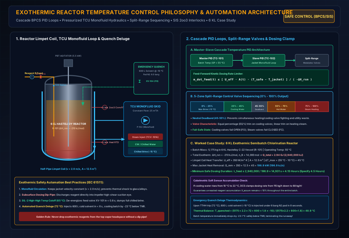
# 1. Executive Summary: The Non-Linear Dynamics of Exothermic Control
In an agitated batch or semibatch reactor, the thermal state of the liquid mass is governed by the dynamic energy balance:
# A. Exponential Chemical Heat Generation ():
The heat release rate () follows an exponential Arrhenius temperature dependence:
# B. Linear Jacket Heat Removal ():
Heat removal through the vessel wall follows Newton's Law of Cooling with a linear temperature dependence:
Heat Rate (q) [kW]
^
|                                          / q_gen (Arrhenius Exponential)
|                                        /
|                                      /
|                                    /
|                    q_rem (Linear) / . . . . Uncontrolled Runaway Zone (q_gen > q_rem)
|                        /        /
|                      /        /
|                    /   o    /  <- Critical Tangent Point: Temperature of No Return (TNR)
|                  /   /
|                /  /  <- Stable Operating Point (q_gen = q_rem)
|              //
|            //
+------------------------------------------------------------>
                                                        Temperature (T) [°C]
# C. Why Single-Loop PID Control Fails Catastrophically:
- Thermal Inertia & Wall Resistance: The heat transfer wall (especially glass-lined steel with or thick Hastelloy shells) introduces a transport lag () between the jacket fluid and the batch. A single-loop PID controller measuring only will continuously over-correct, causing massive thermal cycling and hunting.
- Parametric Sensitivity: As batch temperature approaches the Temperature of No Return (), the open-loop gain of the process approaches infinity, rendering standard linear feedback loops completely unstable.
- Utility Header Disturbances: Fluctuations in plant steam or cooling water header pressures immediately alter heat removal without the master controller detecting it until the batch temperature has already drifted.
# 2. Heat Transfer Geometry & Jacket Hydraulic Architectures
Selecting the proper jacket geometry and utility circulation skid is the first physical line of defense:
+----------------------------------------------------------------------------------------------------+
|                         REACTOR HEAT TRANSFER GEOMETRIES COMPARISON                                |
+------------------------------------+----------------------------------+----------------------------+
| 1. Conventional Plain Jacket       | 2. Half-Pipe Limpet Coil         | 3. Internal Baffle Coils   |
+------------------------------------+----------------------------------+----------------------------+
| * Low utility velocity (< 0.3 m/s) | * High velocity (1.5 - 2.5 m/s). | * Extremely high A/V ratio.|
| * Channeling & stagnant dead-zones.| * High convective h_j (2,500 W/m²K* Submerged in reaction core.|
| * Low pressure rating (< 3.5 barg).| * Pressure rating up to 25 barg. | * Adds 50 - 100% extra area|
| * Unsuitable for fast exotherms.   | * Multi-zone circuits for heels. | * Difficult to clean/CIP.  |
+------------------------------------+----------------------------------+----------------------------+
# A. Conventional Plain Jacket vs. Half-Pipe Limpet Coil:
- Plain Annular Jacket: The large annular gap creates low fluid velocities () and laminar boundary layers with poor heat transfer (). Prone to flow channeling and thermal stratification.
- Half-Pipe Limpet Coil (Industry Best Practice for Exothermic Service):
- Welded semicircular pipe sections () force utility fluid into a high-velocity turbulent spiral ().
- Convective film coefficient increases by ().
- High structural strength allows high-pressure heat transfer fluids ().
- Can be split into multiple independent elevation zones (Bottom Dish Zone, Lower Shell Zone, Upper Shell Zone) to prevent un-wetted wall baking during low liquid heel operations.
# B. The Monofluid Temperature Control Unit (TCU) Hydraulic Philosophy:
In legacy plants, operators directly injected raw steam, cooling water, and chilled brine into the same jacket. This practice is strictly obsolete in modern API manufacturing because:
- Cross-contamination of utility fluids (brine salts corroding steam condensate lines).
- Severe thermal shock fracturing glass-lined reactor walls ().
- Variable jacket flowrates causing the inside heat transfer coefficient () to fluctuate continuously.
                  +-------------------------------------------------------------+
                  |         CLOSED-LOOP MONOFLUID TCU HYDRAULIC SYSTEM          |
                  +-------------------------------------------------------------+
                  |  - Dedicated recirculating pump (v_jacket = CONSTANT 2 m/s) |
                  |  - Constant, maximum heat transfer coefficient (h_j)        |
                  |  - Smooth temperature ramping (Zero thermal shock)          |
                  |  - Single thermal fluid: Syltherm, Marlotherm, or Glycol    |
                  +-------------------------------------------------------------+
                            |                                      ^
        Modulated Hot/Cold  v                                      | Return
        Utility Injection [ Steam / Cooling Water / Chilled Brine ]
The Monofluid Best Practice: A dedicated centrifugal pump continuously recirculates a single thermal fluid (e.g., aqueous ethylene glycol, Syltherm XLT, or Marlotherm) through the limpet coil at constant, high velocity (). Modulating 2-way or 3-way control valves inject hot or cold secondary utility streams into the recirculating loop on demand.
# 3. Advanced Cascade Temperature Control Strategies (BPCS Layer)
To eliminate thermal lag and stabilize exothermic operations, modern DCS architectures deploy Master-Slave Cascade Control with Split-Range Valve Sequencing:
[ Master Reactor Batch Temp PID (TC-101) ]
                  |
                  | (Computes Dynamic Jacket Setpoint T_jacket,SP)
                  v
[ Slave Jacket Monofluid Temp PID (TC-102) ]
                  |
                  | (0% - 100% Controller Output Signal)
                  v
[ 5-Zone Split-Range Control Valve Sequencer ]
   |                  |               |               |                |
   v                  v               v               v                v
[ 0% - 25% ]     [ 25% - 45% ]   [ 45% - 55% ]   [ 55% - 75% ]    [ 75% - 100% ]
Max Chilled      Cooling Tower     Neutral          Hot Water       High-Pressure
Brine (-15 °C)   Water (30 °C)     Deadband          Heating        Steam Heating
# A. Master-Slave Cascade Control Architecture:
- Primary / Master Controller ():
- Process Variable (): Reactor batch temperature ().
- Setpoint (): Target recipe temperature (e.g., ).
- Output (): Dynamically computes the required jacket temperature setpoint ().
- Features: Derivative action with high-frequency noise filter; anti-reset windup clamp ().
- Secondary / Slave Controller ():
- Process Variable (): Jacket recirculating fluid temperature ().
- Setpoint (): Received directly from the Master Controller.
- Output (): Directly modulates the split-range utility control valves ().
- Response Time: Fast loop (), absorbing utility header pressure/temperature disturbances instantly before they affect the reacting batch.
# B. 5-Zone Split-Range Control Valve Sequencing:
A single control signal from the slave PID controller modulates four distinct utility control valves across five operational zones:
| Controller Output () | Active Utility System | Valve Actuation & Action | Trim Characteristic | Primary Control Function |
|---|---|---|---|---|
| Chilled Brine () | Modulates from open () to closed (). Fail Open (FO). | Equal Percentage () | Maximum emergency cooling; suppresses rapid exotherm spikes. | |
| Cooling Tower Water () | Modulates from open () to closed (). Fail Open (FO). | Equal Percentage () | Moderate cooling during steady semibatch reagent addition. | |
| Neutral Deadband | All valves CLOSED. | N/A | Zero utility consumption; prevents simultaneous steam/cooling fighting. | |
| Low-Pressure Steam / Hot Water | Modulates from closed () to open (). Fail Closed (FC). | Linear | Gentle heating during batch warm-up and dissolution. | |
| High-Pressure Steam () | Modulates from closed () to open (). Fail Closed (FC). | Linear | Rapid initial batch heating and reflux distillation. |
# C. Dynamic Feed-Forward Dosing Rate Clamping:
For semibatch exothermic additions (where reactant B is metered into reactant A), the dosing flow controller () must be dynamically clamped by the real-time heat removal capacity of the vessel:
- If cooling water temperature rises or if jacket cooling approaches saturation (), the DCS automatically throttles the dosing pump speed.
- If batch temperature exceeds setpoint by , dosing flow is reduced by ; if temperature exceeds setpoint by , dosing is automatically paused.
# 4. Calorimetric Soft Sensors & Online Reactant Accumulation Tracking
The most dangerous failure in an exothermic semibatch reactor is Silent Reactant Accumulation ():
- If the reactor temperature is operated too low or if catalyst deactivates, reactant B does not react upon entering.
- Reactant B accumulates ().
- When the batch is subsequently warmed up, the entire accumulated inventory reacts simultaneously in an uncontrollable thermal explosion.
                  +-------------------------------------------------------------+
                  |         REAL-TIME DCS CALORIMETRIC SOFT SENSOR              |
                  +-------------------------------------------------------------+
                  |  - Computes instantaneous Q_rxn(t) from jacket delta-T      |
                  |  - Integrates cumulative reaction heat: Integral(Q_rxn) dt  |
                  |  - Compares against total reagent dosed: m_dosed * Delta-H  |
                  |  - Continuously calculates Accumulation Fraction X_accum(t) |
                  +-------------------------------------------------------------+
                                                |
                                                v
                  [ Safety Interlock: If X_accum > 15% -> AUTOMATIC DOSING HOLD ]
# Online Energy Balance Algorithm:
The DCS continuously computes real-time reaction heat release ():
From , the unreacted accumulation fraction () and instantaneous are derived:
The Accumulation Interlock Rule: If or if , the DCS immediately halts reagent dosing and triggers an operator alarm. Dosing cannot restart until the batch exotherm consumes the accumulated inventory.
# 5. Safety Instrumented Systems (SIS / SIL-2 & SIL-3) & Emergency Safeguards
Per IEC 61511 / ISA 84 standards, the Safety Instrumented System must operate on an independent Safety Logic Solver (e.g., Triconex / DeltaV SIS) physically segregated from the DCS:
+----------------------------------------------------------------------------------------------------+
|                         EXOTHERMIC SAFETY INSTRUMENTED SYSTEM (SIS) ARCHITECTURE                   |
+------------------------------+--------------------+------------------------------------------------+
| Hazardous Event / Trigger    | Sensor Logic       | Executive Safety Action (Output State)         |
+------------------------------+--------------------+------------------------------------------------+
| 1. High-High Batch Temp      | TT-101 (2oo3       | • De-energize Reagent Feed Valve XV-101 (< 1s).|
|    (TTHH >= 65 °C)           | voting RTDs)       | • Snap Chilled Brine Valve XV-102 Fail-Open.   |
|                              |                    | • Stop Reagent Feed Pump P-101.                |
+------------------------------+--------------------+------------------------------------------------+
| 2. Thermal Rate-of-Rise Trip | DCS Derivative     | • Hold Reagent Dosing Feed.                    |
|    (dT/dt >= 1.5 °C/min)     | Calculation        | • Pre-emptively ramp cooling to 100%.          |
+------------------------------+--------------------+------------------------------------------------+
| 3. Agitator Shaft Stoppage   | ZSS-101 / IT-101   | • Immediate trip of Reagent Feed Valve XV-101. |
|    (Mixing Failure)          | (Speed + Current)  | • Prevents catastrophic dip-pipe pooling.      |
+------------------------------+--------------------+------------------------------------------------+
| 4. Critical Runaway Point    | TT-101 (2oo3       | • Open Emergency Quench Deluge Valve XV-104.   |
|    (T_batch >= 72 °C ~ TNR)  | voting RTDs)       | • Injects 600 L cold solvent (-10 °C) in < 8s. |
|                              |                    | • Plant Emergency Siren Activation.            |
+------------------------------+--------------------+------------------------------------------------+
| 5. Loss of Power / Air       | Mechanical Spring- | • All Reagent Feed Valves Fail-CLOSED (FC).    |
|    (Blackout Condition)      | Return Actuators   | • Emergency Cooling Valves Fail-OPEN (FO).     |
+------------------------------+--------------------+------------------------------------------------+
# 6. 10 World-Class Best Practices for Exothermic Reactor Engineering
- The Thermal Shock Rule for Glass-Lined Steel (GLR): Never inject cold utility fluid if . Use a closed-loop monofluid TCU to ramp temperature smoothly and prevent glass lining spalling.
- Subsurface Dip-Pipe Dosing with Anti-Siphon Hole: Never drop exothermic reagents from the top dome vapor space (causes vapor flashing and surface pooling). Reagents must be dosed through a subsurface dip pipe discharging directly into the high-shear suction eye of the bottom impeller, with an anti-siphon hole above the maximum liquid level.
- Multi-Elevation Duplex Pt-100 RTDs (2oo3 Voting): Install RTDs at the bottom dish (heel monitoring), mid-height (core reaction zone), and upper level. Wire separate physical elements to BPCS and SIS.
- Fast-Response Thermowells (): Use thin-wall Hastelloy C-22 or Tantalum-tip thermowells packed with thermally conductive silver paste to eliminate measurement lag.
- Coriolis Mass Flow Control on Reagent Feed: Control dosing in true mass () rather than volumetric flow, eliminating temperature-dependent density errors.
- Multi-Zone Limpet Coils for Low Liquid Heels: Partition limpet coils into independent upper and lower circuits so that heating/cooling is applied only to the wetted surface during initial heel operations.
- Emergency Cooling Water Gravity Header / Battery-Backed Circulator: In the event of a total plant blackout, provide a dedicated elevated gravity cooling water tank or UPS-backed circulating pump to maintain heat removal.
- Pressurized Automated Emergency Solvent Quench Pot: Charge a dedicated nitrogen-padded reservoir with cold miscible solvent to dump into the reactor upon SIL-2 temperature trip.
- DIERS Two-Phase Emergency Relief System (ERS): Size rupture disks and safety relief valves for two-phase churn-turbulent flashing flow discharging into a cyclone catch tank.
- Partial Stroke Testing (PST) of Safety Isolation Valves: Configure smart positioners on emergency feed cutoff valves () to perform automated online stroke tests weekly to verify zero mechanical binding.
# 7. Comprehensive Worked Industrial Case Study: 6 KL Semibatch API Chlorination Reactor
# Process Chemistry & Equipment Specifications:
- Synthesis: Highly exothermic semibatch chlorination / alkylation ().
- Reactor: 6,000 L () Hastelloy C-22 Reactor (R-101), Working Volume ().
- Reaction Enthalpy: , Total moles of Reagent B dosed ().
- Operating Temperature: Normal Setpoint , Safe Ceiling .
- Jacket Geometry: Hastelloy C-22 Half-Pipe Limpet Coil (), Wetted Area .
- Overall Heat Transfer Coefficient: (Turbulent monofluid circulation at ).
- Cooling Utility Supply: Chilled water at ().
- Calorimetry (ARC): Adiabatic rise , , Secondary Decomposition (Stoessel Class 4 System).
# Step-by-Step Thermal Engineering Sizing:
# 1. Calculate Maximum Heat Removal Capability ():
# 2. Calculate Minimum Safe Reagent Dosing Duration ():
To ensure chemical heat generation never exceeds maximum jacket cooling ():
Applying a process engineering safety margin of for utility temperature fluctuations:
- Nominal Mass Dosing Rate:
# 3. Sizing the Monofluid TCU Recirculating Pump:
To maintain in a 3-inch half-pipe limpet coil (flow cross-section ):
- Temperature Rise Across Jacket at Peak Exotherm ():
(A narrow delta ensures uniform temperature distribution across the entire reactor height).
# 4. Emergency Quench Deluge Sizing & Thermal Validation:
- Trigger: SIL-2 High-High Temperature Trip at (approaching ).
- Quench Fluid: of cold toluene/heptane at under pad.
- Discharge Time: Injected in through dual high-velocity spray rings.
- Thermal Quench Energy Balance:
- Secondary Dilution Effect: The injected cold solvent dilutes reactant concentrations by , dropping the reaction rate by and permanently stopping the runaway!
# 8. Summary Checklist for Exothermic Reactor Safety Sign-Off
- Limpet Coil Velocity Verified: Monofluid TCU pump sized for in jacket channels.
- Thermal Shock Limits Enforced: DCS programmatically clamps on glass-lined vessels.
- Subsurface Dosing Installed: Dip pipe equipped with anti-siphon hole and positioned near impeller eye.
- Cascade PID Tuning Commissioned: Slave jacket loop tuned with fast response; master batch loop configured with anti-reset windup.
- Dynamic Dosing Limiter Online: Coriolis flowmeter clamped by real-time jacket cooling availability.
- Soft-Sensor Accumulation Interlock Active: Dosing automatically pauses if .
- 2oo3 Voting RTDs Certified: Triplicate duplex RTDs installed at bottom and core reaction zones.
- Fail-Safe Valve Positions Verified: Feed valves fail CLOSED (FC); emergency cooling fails OPEN (FO).
- Emergency Quench Pot Armed: Nitrogen pad pressure ; cold solvent volume verified.
- DIERS ERS Sized: Two-phase relief vent area sized for runaway exotherm with total cooling failure.
# 9. Interactive Process Safety & Reactor Sizing Calculators
Need to compute batch reactor heat transfer areas, evaluate two-phase DIERS relief vents, or model scale-up trajectories?
Launch the Interactive Batch Reactor Scale-Up Calculator →
Launch the Interactive Emergency Relief Vent Sizing Calculator →
Launch the Interactive Heat Exchanger Design Calculator →
Compute multi-scale batch reactor heat transfer coefficients, evaluate Stoessel criticality classes, and size commercial half-pipe limpet coil cooling duties.
# Applicable Engineering Standards & Codes Used
The engineering methodologies, design correlations, and safety criteria detailed in this article adhere to the following international standards and industry codes:
- OSHA 29 CFR 1910.119: Process Safety Management of Highly Hazardous Chemicals
- NFPA 654: Standard for the Prevention of Fire and Dust Explosions from Combustible Particulate Solids
- NFPA 68: Standard on Explosion Protection by Deflagration Venting
- NFPA 69: Standard on Explosion Prevention Systems
- ACGIH Industrial Ventilation: A Manual of Recommended Practice for Design (30th Edition): ACGIH Industrial Ventilation: A Manual of Recommended Practice for Design (30th Edition)
- ISO 28121: Industrial Ventilation and Dust Collection Systems Safety