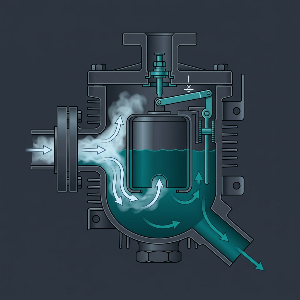
# Steam Traps: The Cheapest Way to Lose 15% of Steam and Not Know It
In chemical and pharmaceutical manufacturing plants, steam is the primary utility for thermal energy transfer—used in reactor jackets, reboilers, evaporators, and Sterilization-In-Place (SIP) loops. Generating dry saturated steam requires significant fuel, boiler water treatment, and electrical energy. Yet, steam systems continuously lose energy through poorly designed or neglected steam traps.
A steam trap is an automatic valve designed to discharge condensate, air, and non-condensable gases from steam lines while preventing the escape of live steam. Statistically, in an un-monitored plant, 15% to 25% of all installed steam traps are in a failed state (either failed open or failed closed). A single medium-sized trap failed open can blow out over of live steam, costing upwards of 12,000 annually in wasted fuel and treated boiler feedwater.
This comprehensive guide details the thermodynamics of steam traps, mathematical sizing formulas, application selection matrices, clean/sanitary steam requirements (ASME BPE), diagnostic auditing workflows, and real-world industrial case studies.
# 1. Thermodynamic Principles: Why Condensate Removal is Critical
When steam transfers heat to a process fluid inside a reactor jacket or heat exchanger, it undergoes a phase change from gas to liquid at constant saturation temperature, releasing its latent heat of vaporization ():
Once latent heat is given up, the steam condenses into water (condensate) at the same temperature. Liquid condensate has a much lower enthalpy than saturated steam, and its thermal conductivity is orders of magnitude lower than condensing steam vapor. If condensate is allowed to back up into heat transfer equipment:
- Reduction in Heat Transfer Coefficient (): Liquid condensate forms a stagnant insulating layer on the heat transfer surface, reducing the overall heat transfer coefficient () by up to .
- Water Hammer: High-velocity steam flowing over accumulated condensate creates waves that form solid liquid slugs. These liquid slugs travel at velocities exceeding , creating massive shock waves (water hammer) upon hitting elbows, valves, or tees, capable of fracturing piping and flanges.
- Corrosion and Carbonic Acid: Non-condensable gases (like and ) dissolved in condensate form carbonic acid, causing pitting corrosion inside steam lines and equipment jackets.
# 2. Steam Trap Sizing & Mathematical Calculations
Sizing a steam trap requires determining the condensate load (, in ) and the effective differential pressure (, in ) across the trap orifice.
# 2.1. Condensate Load Equations
For steady-state heat exchangers:
Where:
- = Condensate flow rate ()
- = Heat duty ()
- = Latent heat of steam at operating pressure ()
For batch process vessel heating (e.g., heating a liquid batch from to in time ):
Where:
- = Mass of process fluid ()
- = Specific heat capacity of process fluid ()
- = Heat-up duration ()
- = Safety Factor / Peak Load Factor (typically to for batch startup loads)
# 2.2. Worked Step-by-Step Calculation Example
Problem: A batch agitated reactor charges of an ethanol-water mixture (). The batch must be heated from to in using saturated steam supplied at (, ). The condensate return header operates at a backpressure of . Calculate the required steam trap discharge capacity.
# Step 1: Calculate Total Heat Required ()
# Step 2: Calculate Average Heat Duty ()
# Step 3: Calculate Base Condensate Generation Rate ()
# Step 4: Apply Safety Factor for Cold Startup ()
At the start of the batch heating cycle, the cold reactor walls condense steam at a rate significantly higher than average. Applying :
# Step 5: Calculate Differential Pressure ()
Design Conclusion: Select a steam trap (e.g., Float & Thermostatic) rated to discharge at least of condensate at .
# 3. Trap Mechanics & Process Application Matrix
Steam traps are categorized into three primary mechanical operational types:
# 3.1. Mechanical Traps (Float & Thermostatic - F&T)
- Operating Principle: Utilizes a buoyancy float connected to a valve mechanism. As condensate enters, the float rises, opening the main discharge orifice proportionally. A secondary thermostatic element releases air during startup.
- Characteristics: Continuous condensate discharge; unaffected by wide pressure fluctuations; excellent air handling.
- Best Application: Jacketed batch reactors, shell-and-tube reboilers, plate heat exchangers, and air heating coils.
# 3.2. Thermodynamic Traps (Disc Traps)
- Operating Principle: Operates on Bernoulli's principle. High-velocity flash steam under the disc creates a low-pressure zone that snaps the disc shut against the seat. When condensate accumulates, lower velocity pressure lifts the disc.
- Characteristics: Intermittent cyclic discharge; extremely rugged; resistant to water hammer and superheated steam; compact size.
- Best Application: High-pressure main steam header drip legs, outdoor steam mains.
# 3.3. Thermostatic Traps (Balanced Pressure Bellows / Bimetallic)
- Operating Principle: Operates on the temperature difference between steam and subcooled condensate. A filled bellows element expands when exposed to hot steam, sealing the orifice.
- Characteristics: Holds back condensate until it subcools below saturation temperature; excellent air venting.
- Best Application: Instrument steam tracing lines, non-critical heating coils, and sanitary clean steam (SIP) vents.
# 3.4. Application Selection Matrix
| Application | Preferred Trap Type | Secondary Option | Key Selection Rationale |
|---|---|---|---|
| Batch Reactor Jacket | Float & Thermostatic (F&T) | Thermostatic (Balanced Press.) | Requires continuous condensate discharge without backing up into heat transfer area. |
| Steam Header Drip Leg | Thermodynamic (Disc) | Float & Thermostatic | Must withstand high pressure, water hammer, and freezing conditions. |
| Reboiler / Heat Exchanger | Float & Thermostatic (F&T) | Float & Lever | Handles high fluctuating heat loads and continuous condensate flow. |
| Clean Steam (SIP) Drain | Sanitary Thermostatic Bellows | Sanitary Membrane Trap | ASME BPE 316L polished design; prevents condensate backing up into sterile fermenters. |
| Steam Tracing Lines | Thermostatic Bimetallic / Bellows | Thermodynamic Disc | Utilizes sensible heat of subcooled condensate, saving steam energy. |
# 4. Sanitary Clean Steam Traps (ASME BPE Compliance for Biopharma)
In biopharmaceutical Sterilization-In-Place (SIP) systems, standard industrial steam traps cannot be used due to cGMP and ASME BPE guidelines:
- Material & Surface Finish: Must be fabricated from 316L Stainless Steel with an internal surface finish of (), electropolished.
- Self-Draining & Uncreviced: Must feature sanitary tri-clamp connections and a body design that ensures complete gravity self-draining when cold, eliminating dead-legs and crevices where bacteria or endotoxins could proliferate.
- Thermostatic Operation: Sanitary thermostatic traps utilize a sealed bellows element that responds rapidly to temperature changes within of steam saturation temperature. This ensures condensate is immediately purged during SIP cycles, keeping sterilization zones at or above ().
# 5. Diagnostic Auditing Workflow & Failure Analysis
Steam traps fail in two primary states, each causing distinct process and economic damage:
- Failed Open (Live Steam Blow-Through): The valve element stays open, allowing live high-pressure steam to blow continuously into the low-pressure condensate return line. This pressurizes the condensate header, causes severe energy loss, and starves adjacent traps of differential pressure.
- Failed Closed (Waterlogging): The valve element remains shut, blocking condensate evacuation. Condensate floods the upstream equipment jacket or pipeline, causing temperature drop, batch processing delays, and severe water hammer.
# 5.1. Diagnostic Testing Techniques
| Testing Technique | Operating Method | Indicator for Failed Open | Indicator for Failed Closed |
|---|---|---|---|
| 1. Visual Inspection | Observe discharge via test tee valve or sight glass. | Continuous high-velocity blue-white live steam jet. | No flow or sluggish cold liquid trickling. |
| 2. Temperature Profiling | Measure inlet vs. outlet piping temperatures using IR Pyrometer. | Inlet and outlet temperatures are equal (zero , high header temp). | Inlet temperature is significantly cold (below ). |
| 3. Ultrasonic Testing | Contact acoustic probe measuring internal ultrasonic frequencies (). | Continuous high-decibel roaring sound without cyclic shutoff. | Complete silence; zero acoustic movement. |
# 6. Industrial Case Studies
# Case Study 1: Clean Steam SIP Loop Sterilization Failure
- The Incident: During a biopharmaceutical fermenter SIP sterilization cycle, the seed fermenter failed temperature validation. Temperature sensors at the lowest condensate drain leg registered , below the required minimum setpoint.
- Root Cause Analysis: Investigation revealed that the sanitary thermostatic bellows trap on the SIP drain line had failed closed due to particulate debris (pipe scale) blocking the small orifice seat. Condensate accumulated up the vertical drain line, creating a cold water barrier that prevented steam contact.
- Consequence: The batch was aborted, resulting in a loss of **36\text{ hours}100\text{-mesh}$ screen and implemented continuous ultrasonic testing on all SIP drain traps.
# Case Study 2: Main Steam Header Water Hammer & Elbow Rupture
- The Incident: Upon opening a main steam supply valve after a weekend plant shutdown, a violent water hammer occurred along a overhead main steam line, resulting in a fractured weld on a pipe elbow and an emergency plant evacuation.
- Root Cause Analysis: The thermodynamic disc trap on the main header drip leg had failed closed due to heavy rust accumulation. Over the weekend, of cold condensate accumulated in the un-drained header. When steam was introduced, it pushed the liquid slug at into the dead-end elbow.
- Corrective Action: Replaced all header drip leg traps with Float & Thermostatic traps equipped with integral blowdown strainers and installed automated warm-up bypass valves.
# 7. Do's and Don'ts Checklist for Steam Trap Systems
| Installation & Operation | DO | DON'T |
|---|---|---|
| Piping Slope | • Slope all steam main lines at least () toward drip legs in the direction of flow. | • Do not run steam piping horizontally flat or sloped backwards toward the boiler. |
| Drip Leg Sizing | • Size drip leg diameter equal to pipe diameter for lines up to , and at least for larger lines. | • Do not tee off a small nipple directly from the bottom of a large steam pipe. |
| Strainer Protection | • Install a Y-strainer with a blowdown valve upstream of every steam trap. | • Do not omit strainers; rust scale will destroy trap orifices within months. |
| Condensate Lift Lines | • Install a check valve downstream of the trap if discharging into an elevated return header. | • Do not count on trap inlet pressure alone to lift condensate without verifying . |
| Group Trapping | • Install an individual dedicated steam trap on every single heat exchanger coil or jacket section. | • Do not "group trap" multiple equipment coils into a single shared trap (causes short-circuiting). |
# 8. Reference Standards Used
- ASME PTC 39: Performance Test Code for Steam Traps.
- ISO 18436-8: Condition Monitoring and Diagnostics of Machines - Ultrasound.
- FCI 69-1: Pressure Rating Standard for Steam Traps (Fluid Controls Institute).
- ASME BPE (Bioprocess Equipment): Part SD (Sanitary Design) & Part MJ (Material Joining).
# Applicable Engineering Standards & Codes Used
The engineering methodologies, design correlations, and safety criteria detailed in this article adhere to the following international standards and industry codes:
- US FDA 21 CFR Part 211: Current Good Manufacturing Practice for Finished Pharmaceuticals
- EU GMP Annex 1: Manufacture of Sterile Medicinal Products
- ISPE Baseline Pharmaceutical Engineering Guide (Vol 1-7: Bulk Active Pharmaceutical Ingredients, Water & Steam Systems): ISPE Baseline Pharmaceutical Engineering Guide (Vol 1-7: Bulk Active Pharmaceutical Ingredients, Water & Steam Systems)
- WHO Technical Report Series No. 961: Supplementary Guidelines on Good Manufacturing Practices for Heating, Ventilation and Air Conditioning