# Industrial Solvent Recovery & Azeotrope Breaking: Packed Column Design and Membrane Separation in Multipurpose API Plants
# Thermodynamic Modeling, Vapor-Liquid Equilibrium (VLE), Structured Packing Hydrodynamics, and Reboiler Safety in Commercial Pharmaceutical Distillation
# Executive Summary
In Active Pharmaceutical Ingredient (API) and fine chemical synthesis, raw materials do not dictate the volumetric bulk of plant operations—solvents do. Between extraction, crystallization, chromatography, and vessel cleanings, organic solvents account for of the total cumulative mass deployed in an API facility.
Disposing of spent mother liquors via high-temperature thermal oxidation (hazardous incineration) is economically crippling and environmentally unsustainable:
- Cost Burden: Incineration costs range from \300 to \800 per metric ton, while virgin pharma-grade solvents continue to escalate in price.
- Scope 1 & 3 Carbon Emissions: Every ton of incinerated solvent releases approximately .
Recovering and purifying spent solvents to cGMP pharmaceutical specifications ( purity, water) cuts API manufacturing costs by . However, pharmaceutical solvent mixtures rarely behave ideally. They frequently form complex minimum-boiling azeotropes, liquid-liquid immiscibility gaps, and thermally sensitive reboiler residues.
This engineering guide details the thermodynamic equations of state, column hydraulic sizing protocols (HETP, F-factor), modern azeotrope-breaking technologies (Pressure-Swing Distillation and Pervaporation), and a fully worked commercial scale-up case study.
# 1. Vapor-Liquid Equilibrium (VLE) & Non-Ideal Activity Coefficients
For an ideal vapor-liquid mixture, Raoult's law applies. In pharmaceutical solvents (such as Isopropanol/Water, Ethyl Acetate/Water, Toluene/Methanol), strong intermolecular forces (hydrogen bonding, dipole interactions) create severe non-ideality:
Where:
- : Operating column pressure ()
- : Vapor and liquid mole fractions of component
- : Pure component vapor pressure at temperature (via Antoine equation)
- : Vapor phase fugacity coefficient ( at low to moderate pressures)
- : Liquid phase activity coefficient
  y_IPA (Vapor Mole Fraction)
  1.0 ┌──────────────────────────────────────────┐
      │                                   • Azeotrope (x = y = 0.68)
      │                           • • • •        │
      │                    • • •                 ▼
      │              • •                         No Separation Possible!
      │          • •                             (Relative Volatility α = 1.0)
      │      • •
      │   • •         Ideal Raoult Curve
      │ •       -----------------
  0.0 └──────────────────────────────────────────┘
      0.0                                      1.0
                 x_IPA (Liquid Mole Fraction)
# 1.1 The Azeotropic Condition
At the azeotropic composition (), the relative volatility () collapses to unity:
At this point, conventional fractional distillation reaches an absolute thermodynamic pinch: no further enrichment is possible regardless of column height or reflux ratio.
# 2. Common Pharmaceutical Azeotropes & Separation Strategies
| Solvent Pair | Type of Azeotrope | Azeotrope Composition | Normal Boiling Point | Industrial Separation Technology |
|---|---|---|---|---|
| Isopropanol (IPA) / Water | Minimum Boiling (Homogeneous) | (Pure IPA: ) | Hydrophilic Pervaporation or Pressure-Swing Distillation (PSD) | |
| Ethanol / Water | Minimum Boiling (Homogeneous) | (Pure EtOH: ) | Zeolite 3A Molecular Sieve Adsorption or Extractive Distillation | |
| Ethyl Acetate / Water | Minimum Boiling (Heterogeneous) | (Pure EtOAc: ) | Decanter-based Heterogeneous Azeotropic Distillation | |
| Tetrahydrofuran (THF) / Water | Minimum Boiling (Homogeneous) | (Pure THF: ) | Pressure-Swing Distillation (Atmospheric 8 bar) | |
| Toluene / Water | Minimum Boiling (Heterogeneous) | (Pure Tol: ) | Gravity Phase Decanter (Water decanted at ambient temp) |
# 3. Advanced Azeotrope Breaking Technologies
                  Option A: Pressure-Swing Distillation (PSD)
┌────────────────────────┐                    ┌────────────────────────┐
│ Low-Pressure Column    │ Overhead Azeotrope │ High-Pressure Column   │ Pure Bottoms
│ (e.g., 0.2 bar Vacuum) │───────────────────►│ (e.g., 6.0 bar Gauge)  │ Component B
└────────────────────────┘                    └────────────────────────┘
                                                         │ Recycled Azeotrope
                                                         ▼ (Back to Column 1)

                  Option B: Hybrid Distillation-Pervaporation
┌────────────────────────┐ Overhead Vapor     ┌────────────────────────┐
│ Fractional Distillation│ (88 wt% IPA / H2O) │ Zeolitic Pervaporation │ Pure Anhydrous IPA
│ Column                 │───────────────────►│ Membrane Skid (NaA)    │ (99.8 wt%)
└────────────────────────┘                    └────────────────────────┘
                                                         │
                                                         ▼ Permeate: Pure Water
# 3.1 Pressure-Swing Distillation (PSD)
Pressure-swing distillation exploits the fact that azeotropic composition is pressure-dependent. By operating two columns in series at different pressures (e.g., Column 1 at vacuum and Column 2 at pressure), the feed to the second column lies outside its new azeotropic envelope, enabling pure product recovery from the bottoms of both towers.
# 3.2 Hydrophilic Pervaporation Membranes
Polymeric or inorganic Zeolite NaA (Linde Type A) ceramic membranes feature molecular pore diameters of .
- Water molecules () pass rapidly through the crystalline lattice under vacuum suction.
- Larger organic solvent molecules (IPA: , Ethanol: ) are completely rejected.
- Energy Advantage: Pervaporation requires energy only to vaporize the small water permeate fraction (), rather than boiling the entire solvent mass multiple times.
# 3.3 Solution-Diffusion Kinetics in Zeolite NaA Membranes
Water transport across a hydrophilic Zeolite NaA molecular sieve membrane is modeled by the solution-diffusion mechanism:
Where:
- : Water permeate flux ()
- : Membrane hydraulic permeance ()
- : Vacuum permeate pressure maintained downstream (typically )
Because the crystalline cages of Zeolite NaA () are strictly smaller than the kinetic diameter of Isopropanol (), the membrane separation factor () exceeds , yielding ultra-pure permeate () and leaving pure anhydrous IPA behind.
# 4. Packed Column Hydraulic Design: Sizing Structured Packing
In multipurpose pharmaceutical plants, corrugated sheet metal structured packing (e.g., Sulzer Mellapak 250Y or 500X) has almost entirely replaced bubble-cap and sieve trays due to its low pressure drop per theoretical stage (), which prevents thermal decomposition of sensitive solvent residues.
# 4.1 F-Factor and Column Diameter Sizing
The column diameter () is determined by the gas capacity F-factor:
Where:
- : Superficial vapor velocity (, in )
- : Vapor density ()
At the flooding point (), liquid downflow is held up by ascending vapor drag. Distillation columns are safely operated at of flood velocity:
# 4.2 Height Equivalent to a Theoretical Plate (HETP)
The total packed height () required to achieve separation is:
- Structured Packing (250 ): .
- Structured Packing (500 ): .
- Random Packing (1-inch SS Pall Rings): .
# 4.3 Fenske-Underwood-Gilliland (FUG) Shortcut Sizing Equations
Before executing rigorous multi-stage ASPEN simulations, process engineers utilize the classical FUG shortcut equations to establish baseline column parameters:
Minimum Theoretical Stages () via Fenske Equation:
Minimum Reflux Ratio () via Underwood Equations:
Where is the Underwood root lying between and , and is the thermal feed condition ( for saturated liquid).
# 5. Reboiler Safety: Peroxides, Foaming, and Thermal Runaway
Solvent distillation reboilers are the site of numerous catastrophic industrial accidents:
[ Reboiler Sump: Long Thermal Residence Time ]
                       │
      ┌────────────────┴────────────────┐
      ▼                                 ▼
Peroxide Concentration (Ethers)    Residue Thermal Decomposition
• THF, 2-MeTHF, Dioxane            • Reactive intermediates / catalysts
• Boiling to dryness concentrates  • Auto-catalytic runaway exotherm
  explosive hydroperoxides!        • Sudden overpressurization!
# 6. Worked Industrial Case Study: Designing a 1,200 kg/h IPA Recovery Skid
# 6.1 Process Specifications
- Feed Stream: Spent crystallization mother liquor: containing Isopropanol (IPA) and Water.
- Target Products:
- Anhydrous IPA: purity (maximum water).
- Stripped Aqueous Effluent: IPA (suitable for biological ETP).
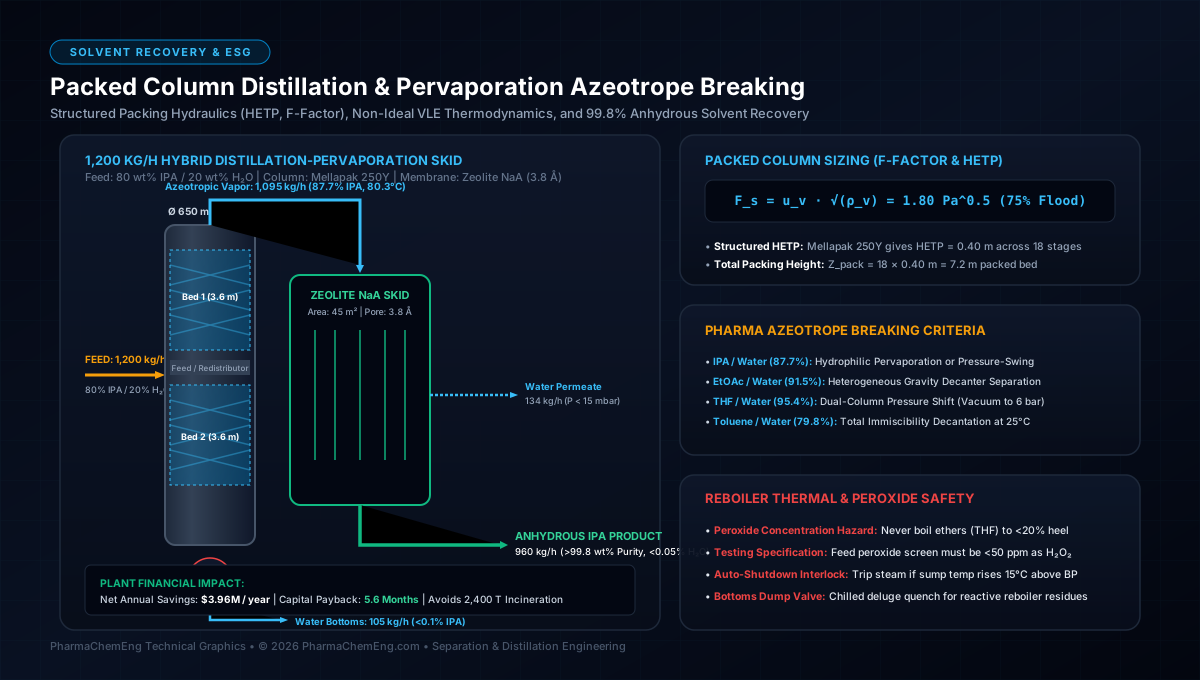
- System Design Selected: Fractional Packed Column (Atmospheric) producing overhead azeotropic vapor ( IPA), coupled directly to an inline Zeolite NaA Pervaporation Membrane Skid.
       Feed (1,200 kg/h: 80% IPA / 20% H2O)
                   │
                   ▼
     ┌───────────────────────────┐
     │ Packed Distillation Tower │ ──► Overhead Azeotrope (1,095 kg/h: 87.7% IPA)
     │ (SS316L, Mellapak 250Y)   │                │
     └─────────────┬─────────────┘                ▼
                   │ Bottoms              ┌──────────────────────────┐
                   ▼ (105 kg/h Water)     │ NaA Pervaporation Skid   │ ──► Permeate: Water (135 kg/h)
                                          └────────────┬─────────────┘
                                                       ▼ Retentate Product
                                            Anhydrous IPA: 960 kg/h (>99.8 wt%)
# 6.2 Distillation Column Sizing Calculations
# Step 1: Mass Balance
- Total IPA in Feed: .
- Overhead Azeotrope Rate ():
- Water Evaporated with Overhead: .
- Bottoms Effluent Rate ():
# Step 2: Minimum Reflux & Stage Requirements
Using ASPEN Plus VLE simulation with NRTL-RK fluid package:
- Minimum Reflux Ratio: .
- Operating Reflux Ratio: .
- Required Theoretical Stages: stages (including reboiler).
# Step 3: Column Internal Diameter ()
At the column top (, ):
- Total vapor traffic: .
- Vapor density: .
- Volumetric vapor flow rate:
- Structured Packing (Mellapak 250Y): .
- Operating at of flood:
- Allowable vapor velocity:
- Column Cross-Sectional Area ():
- Internal Column Diameter:
# Step 4: Packed Height Sizing
- Selecting Mellapak 250Y ():
- Divided into two packed beds with an intermediate liquid redistributor and feed tray.
# Step 5: Pervaporation Membrane Sizing
The overhead vapor from the column ( at IPA) passes into the Zeolite NaA membrane module:
- Water to be removed: .
- High-performance NaA ceramic membrane water flux: at and vacuum permeate pressure.
- Required Membrane Surface Area ():
# 7. Economic Payback & Utility Savings
| Operational Parameter | Baseline (Hazardous Waste Incineration) | Remediated Hybrid Distillation-Pervaporation |
|---|---|---|
| Annual IPA Process Demand | ( recovered) | |
| Virgin Solvent Purchase Cost | \3,600,000 / year (\1.50/kg) | \360,000 / year | | **Hazardous Waste Incineration Cost** | \1,200,000 / year (\0.50/kg) | \120,000 / year |
| Total Annual Operational Cost | \4,800,000 / year** | **\840,000 / year (incl. steam & electricity) | |
| Net Annual Cash Savings | — | \3,960,000 / year** | | **Total System Capital Cost (CapEx)** | — | **\1,850,000 (Payback: 5.6 months) |