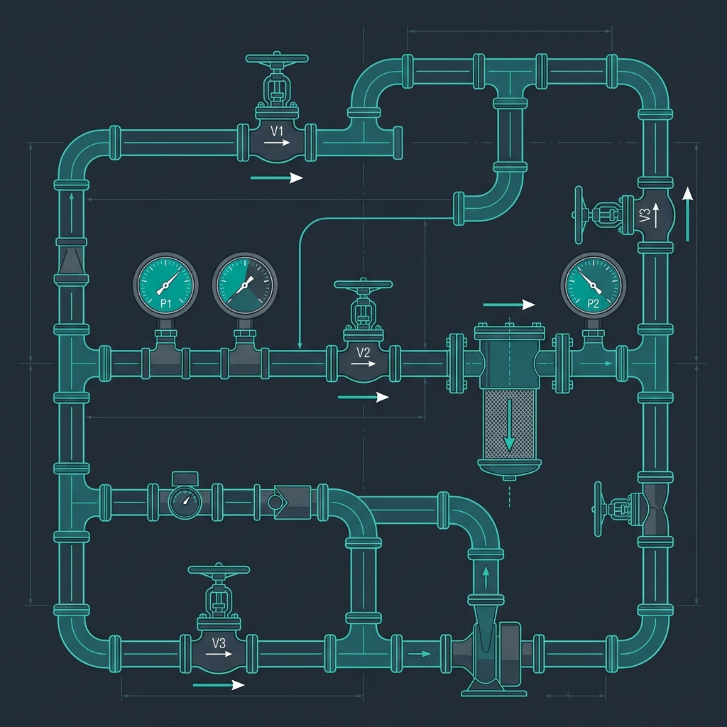
# Pressure Drop: The Complete Practical Guide for Pharma Plant Engineers
For process and plant engineers, sizing lines and calculating pressure drops is a fundamental daily activity. Sizing a pipe too small leads to high velocities, erosion, cavitation in pumps, and elevated utility costs. Sizing too large increases capital costs unnecessarily and creates stagnation zones that violate cGMP cleanliness requirements.
In this guide, we cover the core mathematical equations for fluid hydraulics, fitting losses in sanitary systems, practical pressure budget allocations, and case studies detailing how hydraulic design directly impacts product quality and batch timelines.
# 1. Darcy-Weisbach Equation for Frictional Loss
The fundamental equation for determining frictional pressure drop in a circular pipe is the Darcy-Weisbach equation:
delta_P = f * (L / D) * (rho * v^2 / 200,000)
Where:
- delta_P = Frictional pressure drop (bar)
- f = Darcy friction factor (dimensionless)
- L = Pipe length (m)
- D = Pipe internal diameter (m)
- rho = Fluid density (kg/m³)
- v = Mean flow velocity (m/s)
For laminar flow (Reynolds number Re < 2000), the friction factor is simply:
f = 64 / Re
For turbulent flow (Re > 4000), the Colebrook-White equation is solved. Process engineers should note that the Moody chart friction factor is 4 times the Fanning friction factor, which is a common source of confusion in sizing spreadsheets. Alternatively, the Haaland correlation can be used for explicit calculations:
1 / sqrt(f) = -1.8 * log10( (epsilon/D / 3.7)^1.11 + 6.9 / Re )
# 2. Sanitary Piping Material Roughness
In pharmaceutical facilities, standard carbon steel or rough copper piping is restricted to non-process utilities (cooling water, plant steam). Process-contact piping utilizes high-purity stainless steel tubing with electropolished internal surfaces to prevent microbial adhesion and corrosion.
| Piping Material | Typical Absolute Roughness (epsilon - mm) | Absolute Roughness (epsilon - meters) |
|---|---|---|
| Sanitary Stainless Steel (EP, Ra < 0.4 um) | 0.0015 mm | 0.0000015 m |
| Glass-Lined Steel (Reactors / Receivers) | 0.0010 mm | 0.0000010 m |
| Teflon (PTFE) Lined Piping | 0.0015 mm | 0.0000015 m |
| Commercial Carbon Steel (New) | 0.045 mm | 0.0000450 m |
| Rusting / Aged Carbon Steel | 0.15 mm | 0.0001500 m |
# 3. Minor Losses in Sanitary Fittings (K-Values)
Sanitary fittings use tri-clamp connections rather than threaded joints to eliminate crevices. However, the valves used in sterile loops—specifically diaphragm valves—exhibit much higher hydraulic resistance than standard ball or gate valves.
Minor losses are calculated using the Resistance Coefficient (K) method:
delta_P_minor = Sum(K) * (rho * v^2 / 200,000) bar
# Standard K-Values for Sanitary Fittings (DN25 - 1 inch):
- Sanitary 90° Tri-Clamp Elbow: K = 0.40 to 0.50
- Sanitary 45° Tri-Clamp Elbow: K = 0.20 to 0.25
- Sanitary Diaphragm Valve (Weir-type, Fully Open): K = 2.50 to 4.50 (highly restrictive)
- Sanitary Ball Valve (Full Port): K = 0.05 to 0.10
- Sanitary Tri-Clamp Tee (Through run): K = 0.15 to 0.20
- Sanitary Tri-Clamp Tee (Branch run): K = 1.00 to 1.40
- Sanitary Swing Check Valve: K = 2.00 to 2.50
# 4. Practical Hydraulic Budget & Velocity Guidelines
Process design parameters must balance pressure drop limits against velocity requirements to maintain cGMP standards:
# 4.1. Water for Injection (WFI) & Purified Water (PW) Loops
- Biofilm Prevention: To prevent biofilm growth, water loops must maintain turbulent flow at all times. A minimum return line velocity of 1.5 to 2.0 m/s is standard.
- Pressure Drop Limit: Keep pressure drop below 0.3 bar/100m to prevent thermal buildup from friction, which can heat WFI loop temperatures above the 80°C hot storage limit.
# 4.2. Gravity Decanting & Phase Separations
- Self-Draining Slope: Gravity feed lines must have a minimum slope of 1:100 (1%) and be sized for velocities under 0.8 m/s to prevent air lock or vapor entrainment.
# 4.3. Pump Suction Lines
- Cavitation Avoidance: Keep pressure drops under 0.05 to 0.10 bar/100m. Limit velocities to 0.6 to 1.2 m/s to ensure Net Positive Suction Head Available (NPSHa) exceeds NPSHr by at least 0.5 bar.
# 4.4. Nitrogen & Vacuum Headers
- Nitrogen Header: Sized for 0.05 to 0.15 bar/100m.
- Vacuum Lines (Dryer Exhaust): At absolute pressures of 1 to 10 mbar, vapor volume is enormous. Velocity must be restricted to 15 to 25 m/s to prevent massive pressure drops that choke dryer performance.
# 5. Real-World Case Studies
# Case Study 1: Biofilm Contamination in a PW Loop due to Oversized Piping
- The Problem: A Purified Water loop regularly failed microbiological limits, showing high endotoxin levels. The loop supply pump was operating at its design flow, but velocity in the return header was only 0.5 m/s.
- Root Cause: The return header piping had been oversized (DN50 instead of DN25) to "reduce pressure drop." This design choice dropped the Reynolds number into the laminar/transition zone, allowing bacteria to attach to the electropolished tube walls and grow a biofilm.
- The Solution: Downsized the return header to DN25, raising the velocity to 1.8 m/s. This generated high turbulent shear stress, preventing biofilm attachment and resolving the contamination issue.
# Case Study 2: Vacuum Dryer Bottleneck from Undersized Vapor Line
- The Problem: A vacuum batch dryer was taking 36 hours to dry a solvent wet-cake, compared to the pilot plant timeline of 12 hours. The vacuum pump was maintaining a steady 3.0 mbar, yet solvent evaporation had stalled.
- Root Cause: The vapor line from the dryer to the condenser was DN50 (2-inch). At 3 mbar, the vapor volume of the evaporating solvent was massive, causing a sonic choked flow condition. The pressure drop across the DN50 line was calculated at 4.2 mbar—meaning the dryer vessel pressure was actually at 7.2 mbar (reducing the evaporation rate) while the pump sat at 3.0 mbar.
- The Solution: Replaced the vapor line with a DN100 (4-inch) pipe. This reduced the pressure drop from 4.2 mbar to 0.15 mbar, restoring the dryer vessel pressure to 3.15 mbar and reducing batch drying time to 9.5 hours.
# Case Study 3: Fire Hydrant Ring Main Sizing & Remote Branch Pressure Drop in an API Complex
The Problem: An expanding active pharmaceutical ingredient (API) complex added a new solvent tank farm and high-potency synthesis block located away from the central fire water pump house. During an annual regulatory flow test, fire water was discharged from the three most hydraulically remote hydrant landing valves simultaneously. The plant's high-pressure diesel fire pump was delivering its rated discharge pressure of () at the pump house manifold, but the residual nozzle pressure at the remote tank farm hydrants dropped to an alarming —far below the statutory minimum requirement of (per IS 13039 / TAC) and (per NFPA 14). The weak fire streams could barely reach , creating an unacceptable safety and regulatory risk.
Design Requirements & Hydraulic Basis:
- Simultaneous Fire Flow (): 3 standard landing valves operating at each .
- Fire Water Supply Pressure (): ().
- Static Elevation Difference: The remote tank farm is situated on an elevated pad higher than the pump house manifold.
- Equivalent Piping Length (): Physical straight pipe distance . Adding equivalent lengths for fittings (6 elbows, 2 isolation gate valves, 1 non-return valve, 1 basket strainer) yields an equivalent length .
- Maximum Permissible Water Velocity: (normal design) and strictly during maximum flow (per NFPA 24) to prevent catastrophic water hammer when landing valves are rapidly shut off.
- Statutory Target Residual Pressure: at the highest, most remote hydrant post nozzle.
- Root Cause: The Undersized Single-Dead-End Line (DN100 / 4-Inch Schedule 40 MS Pipe):
The original contractor laid a single dead-end DN100 (, internal diameter ) mild steel line to the tank farm:- Excessive Velocity:
*Violates the maximum velocity limit by more than !* A velocity of causes rapid internal pipe erosion, high turbulence, and catastrophic water hammer risks ( surge shock upon rapid valve closure).
- Severe Frictional Pressure Drop (Hazen-Williams Calculation):
Using the industrial fire water standard Hazen-Williams equation ( for welded mild steel pipe):
Over the equivalent length:
- Residual Pressure at Hydrant:
The line was choking flow through extreme friction, leaving less than at the hydrant post nozzle.
- The Engineering Solutions Compared:
| Engineering Design Parameter | Existing Dead-End DN100 (4-inch) | Upgraded Single Line DN150 (6-inch) | Optimized Looped Ring Main (2 x DN150 Grid) |
|---|---|---|---|
| Nominal Pipe Size | DN100 () | DN150 () | DN150 Looped Ring () |
| Effective Flow Path | Single Dead-End Line () | Single Dead-End Line () | Dual Parallel Loop Paths () |
| Water Velocity () | (UNACCEPTABLE) | (Acceptable) | (OPTIMAL) |
| Hydraulic Friction Loss | |||
| Total Frictional Loss () | |||
| Static Elevation Head Loss | |||
| Residual Hydrant Pressure | (FAILED) | (PASS) | (ROBUST & COMPLIANT) |
| Joukowsky Surge Potential () | (Severe Rupture Risk) | (Safe for Flanges & Fittings) | |
| System Reliability / Redundancy | Zero (Single pipe break stops all water) | Zero (Single pipe break stops all water) | Full Redundancy (Sectional valves isolate leaks) |
- The Final Plant Implementation:
- The single DN100 dead-end line was replaced and extended into a continuous DN150 (6-inch) Closed Ring Main Loop surrounding the new production blocks.
- Because the loop feeds the fire zone from two parallel directions, velocity dropped to a gentle , cutting total friction loss by (from ).
- The final residual hydrant pressure achieved during re-testing was , delivering powerful, high-velocity throw jets that comfortably surpassed all factory insurance and NFPA statutory compliance audits.
# 6. How to Perform Sizing Checks
To calculate fluid velocities, friction factors, and equivalent line lengths for your plant designs, use the interactive Pipe Line Sizing Calculator. Enter your fluid properties (water, steam, or solvents), select the pipe material and schedule, and verify your design against standard hydraulic limits.
# 7. Reference Standards Used
- Crane Technical Paper No. 410: Flow of Fluids Through Valves, Fittings, and Pipe.
- ASME B31.3: Process Piping.
- NFPA 14: Standard for the Installation of Standpipe and Hose Systems.
- NFPA 20: Standard for the Installation of Stationary Pumps for Fire Protection.
- NFPA 24: Standard for the Installation of Private Fire Service Mains and Their Appurtenances.
- IS 13039 / IS 3844: Code of Practice for Fire Protection and Hydrant Systems in Industrial Buildings.
- ISPE Baseline Guide Volume 4: Water and Steam Systems.
# Applicable Engineering Standards & Codes Used
The engineering methodologies, design correlations, and safety criteria detailed in this article adhere to the following international standards and industry codes:
- US FDA 21 CFR Part 211: Current Good Manufacturing Practice for Finished Pharmaceuticals
- EU GMP Annex 1: Manufacture of Sterile Medicinal Products
- NFPA 14 / 20 / 24: Private Fire Service Mains, Pumps, and Standpipe Systems
- IS 13039 / IS 3844: Bureau of Indian Standards Fire Hydrant Codes
- ISPE Baseline Pharmaceutical Engineering Guide (Vol 1-7: Bulk Active Pharmaceutical Ingredients, Water & Steam Systems): Water & Steam Systems
- WHO Technical Report Series No. 961: Supplementary Guidelines on Good Manufacturing Practices for Heating, Ventilation and Air Conditioning