# NPSH Demystified: Why Cavitation Ruins Both Pumps and Batches
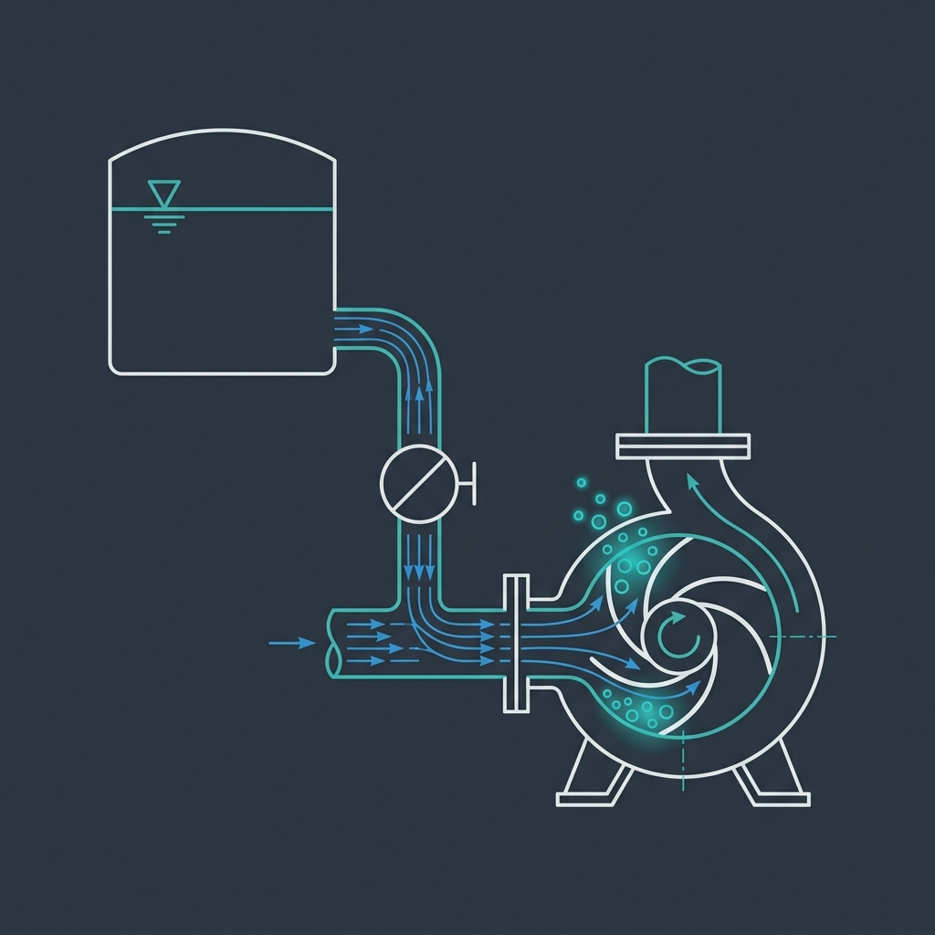
In liquid transportation, process engineers frequently encounter pump failures caused by cavitation. Cavitation is the formation and subsequent violent collapse of vapor bubbles inside a pump. This phenomenon not only damages the pump impeller mechanically but also ruins product batches due to flow interruptions, loss of temperature control, and metal particle contamination.
To prevent cavitation, engineers must master the relationship between Net Positive Suction Head Required (NPSHr) and Net Positive Suction Head Available (NPSHa).
# 1. What is NPSH?
Net Positive Suction Head (NPSH) is the total absolute head (pressure) of liquid at the suction flange of the pump, minus the vapor pressure of the liquid, expressed in feet or meters of head.
- NPSH Required (NPSHr): A physical characteristic of the pump itself, determined by the pump manufacturer through testing. It represents the minimum pressure at the impeller inlet required to keep the liquid from vaporizing. By standard definition, NPSHr is measured at the point where the pump head has dropped by 3% due to cavitation.
- NPSH Available (NPSHa): A property of the piping system design. It represents the actual pressure available in the liquid at the pump inlet flange. NPSHa is calculated by the process engineer based on suction tank pressure, liquid elevation, friction losses, and liquid vapor pressure.
To ensure cavitation-free operation, the golden rule of pump design is:
NPSHa >= NPSHr + Safety Margin (typically 1.0 meter or 3.2 feet)
# 2. Step-by-Step NPSHa Calculation
To calculate NPSHa for a liquid transfer system, use the following formula:
NPSHa = H_static + H_pressure - H_friction - H_vapor
Where:
- H_static = Liquid static height (m or ft) relative to the pump centerline. (Positive if liquid level is above the pump, negative if pump must lift liquid from a sump).
- H_pressure = Absolute pressure on the liquid surface in the supply tank, converted to liquid head (m or ft). For atmospheric tanks, this is atmospheric pressure (approx. 10.13 m of water).
- H_friction = Total friction head losses (m or ft) in the suction piping, including straight pipes, elbows, strainers, and valves.
- H_vapor = Vapor pressure of the liquid at the operating temperature, converted to liquid head (m or ft).
# Temperature Effects on Vapor Pressure:
Vapor pressure increases non-linearly with temperature. For instance, water at 20°C has a vapor pressure of 0.023 bar a (negligible), but at 90°C it rises to 0.70 bar a. This reduces the NPSHa significantly, which is why hot liquid pumps (such as boiler feed pumps or solvent reflux pumps) require high supply tank elevations.
# 3. Practical Sizing Examples
# Example 1: Water Loop Transfer - Cold vs. Hot Sanitization
A Purified Water transfer pump is installed below a WFI storage vessel. The system parameters are:
- Static Height (H_static): Liquid level is 2.0 meters above the pump suction centerline.
- Atmospheric Pressure (H_pressure): 10.13 meters of water head (supply vessel is vented to atmosphere).
- Friction Loss (H_friction): Suction line piping friction is 0.50 meters of head.
- Pump NPSHr: 2.0 meters at design flow rate.
Let's evaluate the system under three different temperatures:
Case A: Operations at 25°C
- Vapor pressure of water = 0.03 bar a (H_vapor = 0.31 meters of head).
- NPSHa = 2.0 + 10.13 - 0.50 - 0.31 = 11.32 meters.
- Margin Check: NPSHa (11.32 m) > NPSHr (2.0 m). Safety margin is 9.32 m. The system is extremely safe.
Case B: Thermal Sanitization at 85°C
- Vapor pressure of water = 0.58 bar a (H_vapor = 5.91 meters of head).
- NPSHa = 2.0 + 10.13 - 0.50 - 5.91 = 5.72 meters.
- Margin Check: NPSHa (5.72 m) > NPSHr (2.0 m). Safety margin is 3.72 m. Still safe from cavitation.
Case C: Thermal Sanitization at 98°C
- Vapor pressure of water = 0.94 bar a (H_vapor = 9.58 meters of head).
- NPSHa = 2.0 + 10.13 - 0.50 - 9.58 = 2.05 meters.
- Margin Check: NPSHa (2.05 m) is almost identical to NPSHr (2.0 m). The safety margin is only 0.05 m. If the suction strainer gets slightly clogged, NPSHa will drop below NPSHr, triggering severe cavitation that will erode the pump impeller and contaminate the loop with metal micro-particles.
# Example 2: Solvent Transfer under Vacuum (Methanol Recovery)
We are pumping methanol out of a vacuum distillation receiver operating at 200 mbar absolute pressure (0.20 bar a). The operating temperature is 35°C.
- Solvent Density (r\rho): 790 kg/m³.
- Vessel Pressure (H_pressure): 0.20 bar a = 20,000 Pa. Head = 20,000 / (790 * 9.81) = 2.58 meters.
- Methanol Vapor Pressure (H_vapor): At 35°C, vapor pressure is 0.27 bar a = 27,000 Pa. Head = 27,000 / (790 * 9.81) = 3.48 meters.
- Friction Loss (H_friction): 0.30 meters.
- Pump NPSHr: 2.00 meters.
Because the liquid is under vacuum, H_vapor is greater than H_pressure (3.48 m > 2.58 m). The liquid is close to its boiling point. Let's calculate the minimum static height (H_static) required to maintain a 1.0-meter safety margin (NPSHa >= 3.00 m):
NPSHa = H_static + H_pressure - H_friction - H_vapor >= 3.00 m
H_static + 2.58 - 0.30 - 3.48 >= 3.00
H_static - 1.20 >= 3.00
H_static >= 4.20 meters
Engineering Solution: To prevent cavitation, the distillation receiver must be installed on a steel platform at least 4.20 meters above the pump suction centerline.
# 4. Industrial Case Study: Acetone Transfer Pump Cavitation
During a greenfield pharmaceutical expansion, an API transfer pump was designed to move raw acetone from an outdoor storage vessel to an indoor reactor. The process engineer calculated the NPSHa during winter conditions, determining a comfortable margin of 1.5 meters over the pump's NPSHr of 2.0 meters.
However, during summer commissioning, the ambient temperature reached 38°C, raising the acetone temperature. The vapor pressure of the acetone increased from 0.24 bar a to 0.55 bar a. This cut the NPSHa down to 1.1 meters, well below the pump's NPSHr.
The pump began to operate with a loud rattling noise, resembling "pumping gravel." The flow rate dropped by 40%, preventing the solvent from reaching the reactor on time, which ruined a batch of temperature-sensitive crystalline intermediates. The impeller was severely pitted and had to be replaced.
# The Fix:
The suction line diameter was expanded from 2 inches to 3 inches, reducing suction velocities and cutting friction loss (H_friction) by 80%. This restored the NPSHa margin to 1.2 meters under worst-case summer conditions.
# 5. Sizing Tools
To calculate fluid vapor pressure using Antoine coefficients, determine friction losses, and verify pump NPSHa margins, use the Pump Sizing Calculator.
# 6. Reference Standards Used
- ANSI/HI 1.3 (Hydraulic Institute): Centrifugal Pumps for Design and Application.
- ANSI/HI 9.6 (Hydraulic Institute): Rotary Pumps for NPSH Margin Requirements.
- API 610: Centrifugal Pumps for Petroleum, Petrochemical, and Natural Gas Industries.
# Applicable Engineering Standards & Codes Used
The engineering methodologies, design correlations, and safety criteria detailed in this article adhere to the following international standards and industry codes:
- ASME B31.3: Process Piping Code
- API RP 14E: Recommended Practice for Design and Installation of Offshore Production Platform Piping Systems
- Hydraulic Institute Standards (HI 1.3, HI 2.3) for Centrifugal and Positive Displacement Pumps: Hydraulic Institute Standards (HI 1.3, HI 2.3) for Centrifugal and Positive Displacement Pumps
- ISO 5167: Measurement of Fluid Flow by Means of Pressure Differential Devices