# Pharma Equipment Surface Area Calculation for Cleaning Validation, MACO & Solvent Quantity Requirements: Reactors, ANFDs, Multi-Mills & Synthesis Trains
# 1. Introduction: Why Surface Area Precision is Critical in Cleaning Validation
In multipurpose Active Pharmaceutical Ingredient (API) and solid dosage manufacturing facilities, cross-contamination between successive product campaigns is one of the most heavily scrutinized areas during regulatory audits (FDA 21 CFR Part 211.67, EU GMP Annex 15, PIC/S PI 006-3, and ICH Q7).
The scientific benchmark for assessing cleaning efficacy is the Maximum Allowable Carryover (MACO)—the maximum quantity of a previous active drug substance allowed to remain on shared equipment surfaces without posing a toxicological or therapeutic risk in the subsequent product batch.
However, calculating the Allowable Surface Residue Limit ( in ), setting analytical swab action limits (), and determining the cleaning rinse solvent volume () strictly depend on knowing the exact total internal wetted surface area () of the equipment train. Over-estimating surface area produces falsely high residue limits, risking cross-contamination; under-estimating surface area results in unnecessary cleaning cycles, excessive solvent waste, and extended downtime.
# 2. Equipment Surface Area Vectors & MACO Sizing Architecture
The engineering layout below illustrates the wetted surface area components for three core pharmaceutical unit operations—Chemical Reactors, Agitated Nutsche Filter Dryers (ANFD), and Multi-Mills—along with the APIC / FDA MACO calculation framework:
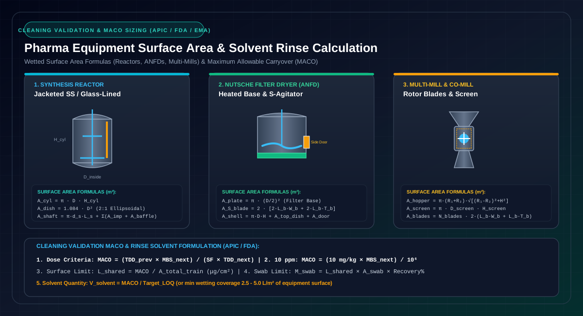
Interactive Engineering Tool: Automatically compute equipment surface areas, MACO limits, and cleaning solvent quantities using our interactive Pharma Equipment Surface Area & Cleaning Validation Calculator.
# 3. Detailed Equipment Surface Area Geometric Formulas
# 3.1 Jacketed Chemical Batch Reactor (SS316L / Glass-Lined)
In a batch reactor, the total internal wetted surface area () is the sum of the cylindrical shell, top and bottom dished heads, agitator shaft, impeller blades, baffles, and nozzles:
# A. Cylindrical Shell:
Where is the inside diameter and is the straight tan-to-tan shell height.
# B. Dished Heads (Top & Bottom):
The surface area of formed dished heads depends on geometry:
- 2:1 Semi-Ellipsoidal Head (Standard Industrial API Reactor):
- Torispherical Head (Klöpper Type, ):
- Hemispherical Head:
- Flat Flanged / Conical Bottom:
# C. Agitator Shaft & Multi-Tier Impeller Blades:
- Shaft Area:
- Pitched Blade Turbine (PBT) / Hydrofoil / Retreat Curve (RCI):
(Rule of thumb for standard dual PBT: per tier)
- Anchor Impeller (Close-Clearance):
# D. Baffles & Internal Nozzles:
- Baffles (3 or 4 Beaver-Tail / Flat Blades):
- Nozzle Necks & Dip Legs:
# 3.2 Agitated Nutsche Filter Dryer (ANFD)
An ANFD features a wide-diameter low-height cylindrical shell, a heated porous sintered filter base plate, S-curved hollow heated agitator blades, a side discharge plug door, and internal hydraulic bellows:
- Filter Base Plate Area (Including Sintered Wire Mesh & Support Rings):
- S-Curved Hollow Heated Agitator Blade (Top face, Bottom face, and Heated leading/trailing edges):
- Side Cake Discharge Port:
- Agitator Shaft Bellows (Protective SS Bellows):
# 3.3 Milling & Size Reduction Equipment (Multi-Mill / Co-Mill)
For dry powder milling, all internal product-contact surfaces must be quantified:
- Conical Feed Hopper (Frustum of a Cone):
Where is the top inlet radius, is the bottom discharge radius, and is the cone height.
- Milling Chamber Housing:
- Rotor Impeller (12 High-Speed Knife/Impact Blades):
- Perforated Screen Mesh Cylinder:
- Discharge Chute:
# 3.4 Process Centrifuges & Transfer Piping
- Peeler / Vertical Centrifuge Basket & Curb:
- Process Transfer Piping Loops & Hoses:
# 4. Maximum Allowable Carryover (MACO) Formulations (APIC / FDA / EMA)
Per the APIC Guide on Aspects of Cleaning Validation in API Plants, MACO is evaluated across three scientific criteria. The most stringent (lowest) value governs the validation acceptance protocol:
# 4.1 Criterion 1: Therapeutic Daily Dose (1/1000th Dose Rule)
No more than () of the minimum therapeutic daily dose of the previous product should be carried over into the maximum daily dose of the subsequent product:
Where:
- = Minimum daily therapeutic dose of previous API (mg/day)
- = Minimum batch size of subsequent product (mg or kg)
- = Maximum daily therapeutic dose of subsequent product (mg/day)
- = Safety Factor ( for oral solid dose APIs; for potent, injectable, or ophthalmic formulations)
# 4.2 Criterion 2: 10 ppm Default Toxicological Limit
Not more than () of the previous active ingredient is permitted in the subsequent batch:
# 4.3 Criterion 3: Health-Based Exposure Limit (ADE / PDE per EMA Guidelines)
Based on toxicological Permitted Daily Exposure (PDE) or Acceptable Daily Exposure (ADE) determined from animal NOAEL / LOAEL data:
# 5. Allowable Surface Limits & Swab Action Limits
Once the governing MACO ( in mg) is selected:
# 5.1 Shared Surface Carryover Limit ()
# 5.2 Analytical Swab Sample Action Limit ()
When taking swab samples using a standard sampling template ( for or for ):
Where is the experimentally validated swab extraction recovery ().
# 6. Cleaning Solvent Quantity Requirements ()
Determining the proper solvent volume ( in Liters) for cleaning validation rinses requires balancing physical hydraulic wetting against analytical instrument sensitivity:
# 6.1 Method A: Analytical Detection Limit ()
To ensure that any residue at the MACO limit will produce a concentration in the final rinse that is above the analytical method's Limit of Quantitation ():
# 6.2 Method B: Minimum Hydraulic Surface Wetting Volume ()
For dynamic spray balls and CIP orbital nozzles, adequate liquid film cascade requires:
Where of equipment surface area.
# 6.3 Method C: Agitation Boil-Up / Reflux Wash Volume
For batch synthesis reactors, a liquid charge of of nominal volume is required to completely submerge the bottom agitator blade and generate vigorous vapor reflux across the upper shell, dished head, and vapor line.
# 7. Comprehensive Worked Engineering Case Study: Multi-Equipment API Synthesis Train
# 7.1 Manufacturing Train Description:
A dedicated campaign of Previous API (Product A) is completed, followed by changeover to Next API (Product B) across a 5-unit shared synthesis train:
- Reactor (R-101): Jacketed SS316L Reactor (, 2:1 Ellipsoidal Heads, Dual PBT Impellers)
- Centrifuge (CF-101): Vertical Peeler Centrifuge
- Filter Dryer (FD-601): Agitated Nutsche Filter Dryer ()
- Multi-Mill (MM-101): High-Speed Rotor & Perforated Screen Mill
- Transfer Piping (PL-101): of 2" NB SS316L Piping
# 7.2 Toxicological & Batch Parameters:
- Product A (Previous): Min Daily Dose , , Safety Factor
- Product B (Next): Min Batch Size , Max Daily Dose
- Swab Template: (), Analytical Recovery
- Analytical HPLC LOQ: ()
# 7.3 Step-by-Step MACO & Cleaning Sizing:
- Therapeutic Dose-Based MACO:
- 10 ppm Default MACO:
- PDE Health-Based MACO:
- Governing Acceptance Limit:
- Allowable Surface Carryover Limit ():
- Swab Sample Action Limit ():
- Cleaning Solvent Quantity Requirements ():
- Method A (Maximum volume for LOQ):
- Method B (Minimum hydraulic wetting volume at ):
- Method C (Operational Recommended Charge):
- For Reactor R-101 ( boil-up heel):
- For ANFD FD-601 (base rinse & spray):
- For Centrifuge & Lines:
- Total Recommended Train Rinse Solvent: (producing a safe analytical concentration of ).
# 8. Summary of Best Practice Engineering Rules
- Include All Internal Fixtures: Never calculate simple cylinder volume; always include impeller blades, bottom valves, dip legs, baffles, and nozzles.
- Apply Worst-Case Train Envelope: If a piece of equipment is shared between multiple synthesis routes, use the smallest subsequent batch size () and most potent previous API.
- Validate Swab Recovery: Perform lab coupon recovery studies (, Glass, PTFE) across three concentration levels (, , and of swab limit).
- Balance Solvent Volumes: Verify that the solvent rinse volume produces a concentration well above the analytical method's LOQ while remaining below the MACO threshold.
# 9. Governing Quality & Regulatory Standards
- APIC (Active Pharmaceutical Ingredients Committee): Guidance on Aspects of Cleaning Validation in API Plants (May 2014).
- FDA 21 CFR Part 211.67: Equipment Cleaning and Maintenance.
- FDA Guidance: Guide to Inspections of Validation of Cleaning Processes (7/93).
- EMA/CHMP/CVMP/SWP/169430/2012: Guideline on setting health based exposure limits for use in risk identification in the manufacture of different medicinal products in shared facilities.
- PIC/S PI 006-3: Validation Master Plan, Installation and Operational Qualification, Non-Sterile Process Validation, Cleaning Validation.
- ASTM E3106-18e1: Standard Guide for Science-Based and Risk-Based Cleaning Process Development and Validation.
- ICH Q7: Good Manufacturing Practice Guide for Active Pharmaceutical Ingredients.
# Applicable Engineering Standards & Codes Used
The engineering methodologies, design correlations, and safety criteria detailed in this article adhere to the following international standards and industry codes:
- US FDA 21 CFR Part 211: Current Good Manufacturing Practice for Finished Pharmaceuticals
- EU GMP Annex 1: Manufacture of Sterile Medicinal Products
- ISPE Baseline Pharmaceutical Engineering Guide (Vol 1-7: Bulk Active Pharmaceutical Ingredients, Water & Steam Systems): ISPE Baseline Pharmaceutical Engineering Guide (Vol 1-7: Bulk Active Pharmaceutical Ingredients, Water & Steam Systems)
- WHO Technical Report Series No. 961: Supplementary Guidelines on Good Manufacturing Practices for Heating, Ventilation and Air Conditioning