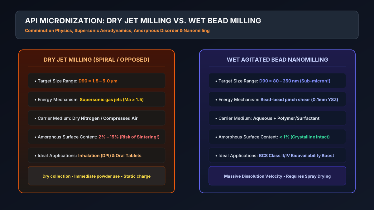
# Jet Milling vs. Wet Bead Milling: The Physics of API Micronization () for Inhalation & Poorly Soluble Drugs
# A Masterclass on Fracture Mechanics, Sonic Nozzle Aerodynamics (), Centrifugal Classifier Sizing, Amorphous Surface Disorder, and Media Wear Kinetics
# Executive Summary & Industrial Stakes
Over of small-molecule new chemical entities (NCEs) in pharmaceutical pipelines are classified as BCS Class II or Class IV—compounds characterized by low aqueous solubility. For oral solid dosage forms, the rate of drug absorption is fundamentally limited by dissolution velocity, governed by the Noyes-Whitney equation:
Where:
- = Total effective surface area of API crystals ()
- = Solute diffusion coefficient ()
- = Diffusion boundary layer thickness ()
- = Equilibrium saturation solubility ()
- = Bulk fluid concentration ()
Because specific surface area scales inversely with particle diameter (), reducing crystal size from down to increases surface area by over , transforming poorly bioavailable compounds into commercial therapies. Furthermore, for Dry Powder Inhalers (DPI), lung deposition demands strictly Aerodynamic Diameters between and ; particles larger than impact the oropharynx, while those smaller than are exhaled without therapeutic benefit.
┌──────────────────────────────────────────────────────────────────────────────────────────────────┐
│                             DRY JET MILLING VS. WET BEAD NANOMILLING                             │
├────────────────────────────────┬────────────────────────────────┬────────────────────────────────┤
│ Engineering Parameter          │ Dry Spiral / Opposed Jet Mill  │ Wet Bead Nanomill (Agitated)   │
├────────────────────────────────┼────────────────────────────────┼────────────────────────────────┤
│ Achievable Particle Size       │ D90: 1.5 – 5.0 μm              │ D90: 80 – 400 nm (Sub-micron!) │
│ Continuous Fluid Medium        │ Compressed N₂ / Clean Dry Air  │ Aqueous / Stabilizer Solution  │
│ Energy Dissipation Mechanism   │ Inter-particle sonic collision │ Hydrodynamic shear & bead pinch│
│ Surface Disorder (Amorphous)   │ Moderate to High (2 – 15%)     │ Minimal (Protected by liquid)  │
│ Electrostatic Tribocharging    │ Severe (Fluidization charges)  │ None (Conductive liquid matrix)│
│ Post-Processing Requirement    │ Direct blending / capsule fill │ Isolation, Spray Drying/Lyophil│
│ Target Dosage Form             │ Inhalation (DPI) & Oral Tablets│ Fast-melt tablets, injectables │
└────────────────────────────────┴────────────────────────────────┴────────────────────────────────┘
This guide details the physics of crystal comminution, supersonic gas jet mechanics, classifier cut size equations, amorphous disorder generation, and wet nanomilling kinetic models.
# 1. Fracture Mechanics & Energy Comminution Laws
Brittle crystalline organic materials fracture when applied mechanical stresses exceed the crystal's critical stress intensity factor (), causing microcrack propagation according to Griffith's theory:
Where:
- = Tensile fracture stress ()
- = Young's modulus of elasticity ()
- = Surface free energy ()
- = Pre-existing flaw/microcrack length ()
As particles become smaller, the probability of finding a critical flaw () decreases exponentially. Consequently, smaller crystals exhibit significantly higher mechanical strength than bulk crystals. Below the brittle-to-ductile transition limit ( for organic molecular crystals), mechanical impact no longer produces brittle cleaving; instead, plastic deformation and surface melting occur.
                          ENERGY REQUIRED VS. PARTICLE SIZE
    Specific Energy (kWh/tonne)
      ▲
 1000 ┼                                                     ╭── Rittinger's Law
      │                                                     │   (E ∝ 1/d) - Nanomilling
  100 ┼                                         ╭───────────╯
      │                              ╭──────────╯ Bond's Law (E ∝ 1/√d) - Jet Milling
   10 ┼                  ╭───────────╯ Kick's Law (E ∝ ln(d₀/d)) - Coarse Crushing
      │                  │
    1 ┴──────────────────┴──────────┴──────────┴──────────┴──────────►
     10 mm             1 mm       100 μm      10 μm      1 μm     100 nm
The general differential energy law of comminution is:
- Kick's Law (): Valid for coarse crushing (), where energy is proportional to the volume reduction ratio.
- Bond's Law (): Valid for intermediate grinding ().
- Rittinger's Law (): Valid for fine micronization and nanomilling (), where energy consumption is directly proportional to new surface area created:
# 2. Dry Jet Milling: Supersonic Gas Aerodynamics & Classifier Cut Size
In dry jet milling, high-pressure nitrogen or clean dry air () accelerates through convergent-divergent De Laval nozzles, expanding into the grinding chamber at supersonic velocities (, ).
                    SPIRAL JET MILL VS. OPPOSED BED JET MILL
 ┌──────────────────────────────────────────────────────────────────────────────────────────────────┐
 │                                                                                                  │
 │ OPTION 1: SPIRAL JET MILL (PANCAKE)              OPTION 2: OPPOSED FLUIDIZED BED JET MILL        │
 │                                                                                                  │
 │                Feed Funnel & Venturi                               Exhaust to Cyclone / Baghouse │
 │                        │                                                        ▲                │
 │                        ▼                                                        │                │
 │       ┌────────────────────────────────┐                        ┌───────────────┴────────┐       │
 │       │        GRINDING CHAMBER        │                        │ Dynamic Classifier     │       │
 │       │        (Pancake Vortex)        │                        │ Wheel (High-Speed RPM) │       │
 │       │  ▲                          ▲  │                        └───────────────┬────────┘       │
 │       └──┼──────────────────────────┼──┘                                        │ Rejected Fines │
 │          │ Peripheral Gas Nozzles   │                                           ▼                │
 │       (Supersonic Tangential Inlets)│                        ┌───────────────────────────────┐   │
 │                                                              │ Fluidized Bed Grinding Zone   │   │
 │                                                              │  ◄── Gas Jet     Gas Jet ──►  │   │
 │                                                              │      (Opposed Impingement)    │   │
 │                                                              └───────────────────────────────┘   │
 └──────────────────────────────────────────────────────────────────────────────────────────────────┘
# 2.1 Spiral (Pancake) Jet Mill Mechanics
- Feed crystals are sucked into the chamber via a Venturi nozzle driven by grinding gas.
- Tangential grinding nozzles create a high-speed spiral vortex. Centrifugal force pushes coarse particles to the outer perimeter, where they are repeatedly struck by fresh gas jets and other crystals.
- Drag force carries small particles inward toward the central discharge port.
The cut-off particle diameter () is defined by the balance between inward fluid drag force and outward centrifugal force:
Solving for :
Where:
- = Gas dynamic viscosity ()
- = Radial inward gas velocity ()
- = Tangential swirling gas velocity ()
- = Radius of the classifier zone ()
- = Solid particle true density ()
# 2.2 Opposed Fluidized Bed Jet Mill with Dynamic Classifier
- Gas nozzles face each other at the bottom of a fluidized bed. Particles collide exclusively in the focal center of the gas streams, eliminating wall impact and abrasive equipment wear.
- A variable-speed rotating centrifugal classifier wheel sits above the bed. Only particles fine enough to overcome the wheel's centrifugal field pass through to the cyclone collector.
# 3. The "Amorphous Surface Disorder" Trap in Dry Jet Milling
During high-velocity impacts (), instantaneous point temperatures at crystal collision contact points can reach for microseconds, exceeding the API melting point.
This localized flash-melting quenches into an amorphous surface disorder skin ( amorphous content) over an otherwise crystalline core:
                  AMORPHOUS SURFACE GENERATION & RECRYSTALLIZATION
 ┌─────────────────────────┐   Humidity / Ambient H₂O   ┌─────────────────────────┐
 │   Freshly Milled API    │ ─────────────────────────► │   Aged / Agglomerated   │
 │ ┌─────────────────────┐ │     Plasticization &       │ ┌─────────────────────┐ │
 │ │ Crystalline Core    │ │   Recrystallization        │ │ Bridged Agglomerate │ │
 │ │                     │ │                            │ │ (Concrete Hard!)    │ │
 │ ├─────────────────────┤ │                            │ ├─────────────────────┤ │
 │ │ Amorphous Skin      │ │                            │ │ Inter-particle Sinter││
 │ └─────────────────────┘ │                            │ └─────────────────────┘ │
 └─────────────────────────┘                            └─────────────────────────┘
   High Tribocharge, Metastable                           Loss of Inhalation FPF!
Amorphous surfaces are hygroscopic and thermodynamically metastable. Upon exposure to ambient humidity (), moisture acts as a plasticizer, lowering the surface glass transition temperature () below room temperature.
The amorphous layers rapidly recrystallize, forming solid crystalline bridges (sintering) between adjacent particles. A freshly milled batch with can consolidate into hard agglomerates with within 48 hours!
# Engineering Solution: Controlled Conditioning & Cryo-Jet Milling
- In-Line Conditioning: Store freshly jet-milled API in a temperature- and humidity-controlled chamber () under fluidized nitrogen for 4 to 12 hours. This forces controlled surface relaxation before final blending.
- Cryogenic Jet Milling: Cool grinding nitrogen gas to using an in-line heat exchanger, suppressing localized surface flash-melting and maintaining crystallinity .
# 4. Wet Bead Milling (Nanomilling): Sizing & Physics for Sub-Micron APIs
When target sizes fall below (), dry jet milling fails due to ductile limit cushioning and severe electrostatic agglomeration. In this domain, agitated wet media nanomilling is the gold standard.
                      AGITATED WET BEAD NANOMILL SCHEMATIC
 ┌──────────────────────────────────────────────────────────────────────────────────────────────────┐
 │                                                                                                  │
 │   Chilled Water Cooling Jacket (-5°C)                                                            │
 │   ┌──────────────────────────────────────────────────────────┐                                   │
 │   │  Milling Chamber with Micro-Beads (0.1 - 0.5 mm YSZ)     │                                   │
 │   │                                                          │                                   │
 │   │      ┌───┐            ┌───┐            ┌───┐             │                                   │
 │   │======│   │============│   │============│   │====== Shaft │ ◄── Tip Speed v_tip = 10 - 14 m/s │
 │   │      └───┘            └───┘            └───┘             │                                   │
 │   │    Agitator Pegs / Discs (Zirconia or Polyurethane)      │                                   │
 │   │                                                  ┌─────┐ │                                   │
 │   │                                                  │Screen│─► Nanoparticle Slurry Outlet       │
 │   └──────────────────────────────────────────────────┴─────┴─┘  (D90 = 180 nm, Stabilized)       │
 │                                                                                                  │
 └──────────────────────────────────────────────────────────────────────────────────────────────────┘
# 4.1 Stress Model: Stress Energy () and Stress Number ()
Grinding kinetics in wet bead mills are governed by Kwade's Stress Model:
- Stress Energy (): The kinetic energy available per bead-bead collision:
Where:
- = Grinding media bead diameter ()
- = Bead material density ( for Yttria-Stabilized Zirconia - YSZ)
- = Rotor circumferential tip speed ()
- Stress Number (): The total number of collision events experienced by an API crystal:
Where is the bead volumetric filling ratio ().
Using beads that are too large () wastes energy in over-stressing (causing crystal lattice damage and high zirconic bead wear). Using beads that are too small () produces collisions with insufficient kinetic energy to crack crystals.
Rule of Thumb: Optimal bead diameter is approximately to the initial feed crystal size (). For , start with or YSZ beads.
# 5. Industrial Equipment Selection & Troubleshooting Matrix
┌─────────────────────────┬─────────────────────────┬─────────────────────────┬─────────────────────────┐
│ Operational Challenge │ Root Cause Mechanism │ Equipment Affected │ Engineered Remedy │
├─────────────────────────┼─────────────────────────┼─────────────────────────┼─────────────────────────┤
│ Jet Mill Venturi Blow- │ Feed hopper bridge; │ Spiral Jet Mill │ Adjust Venturi motive │
│ back (Powder Ejection) │ chamber operating │ │ pressure ;│
│ │ pressure > Venturi vac │ │ install vibrating chute │
├─────────────────────────┼─────────────────────────┼─────────────────────────┼─────────────────────────┤
│ Severe Agglomeration │ Triboelectric charging │ Opposed Jet Mill │ Add aerosol│
│ in Inhalation Powder │ causing high particle │ │ magnesium stearate as a │
│ │ adhesion energy │ │ force-control agent │
├─────────────────────────┼─────────────────────────┼─────────────────────────┼─────────────────────────┤
│ Bead Screen Clogging / │ Media compaction against│ Wet Bead Nanomill │ Reverse rotor spin for │
│ Pressure Spike in Mill │ separator screen due to │ │ 5 seconds; reduce slurry│
│ │ high slurry viscosity │ │ feed rate; add HPC/PVP │
├─────────────────────────┼─────────────────────────┼─────────────────────────┼─────────────────────────┤
│ Heavy Zirconium Bead │ Rotational tip speed │ Wet Bead Nanomill │ Drop from 14 to│
│ Wear Contamination │ excessive ();│ │ ; switch from │
│ (> 10 ppm Zr in API) │ empty bead churning │ │ steel pegs to YSZ ceramic│
└─────────────────────────┴─────────────────────────┴─────────────────────────┴─────────────────────────┘
# 6. Key Chemical Engineering Rules of Thumb
- Inhalation Window: Target aerodynamic diameter strictly between and .
- Venturi Differential: Always set the Venturi injection gas pressure at least higher than the grinding ring manifold pressure to prevent blowback.
- Moisture Control: Feed gas dew point must be strictly lower than . Moisture in grinding gas creates immediate nozzle freezing and cake plastering on the chamber perimeter.
- Wet Nanomill Filling: Maintain bead filling ratio between and of free chamber volume. Operating below drops milling kinetics by over .
Published by the PharmaChemEng Technical Editorial Board for pharmaceutical formulation scientists, particle development engineers, and process technology teams.