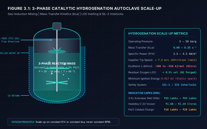
# Hydrogenation Reactor Design: Scale-up, Mass Transfer & Process Safety
# Executive Summary
Hydrogenation in Active Pharmaceutical Ingredient (API) and specialty chemical manufacturing represents one of the most critical and hazardous unit operations. It involves a multiphase reaction network—typically gas-liquid-solid (G-L-S)—operating under elevated pressures (5 to 100 bar) and elevated temperatures (50°C to 180°C), utilizing highly pyrophoric heterogeneous catalysts (e.g., Palladium on Carbon, Platinum on Carbon, Raney Nickel) with highly flammable hydrogen gas.
Successful scale-up from a 500 mL laboratory autoclave to a 3,000 L commercial production vessel requires a rigorous, quantitative analysis of gas-liquid volumetric mass transfer rate (), heat removal capability (), catalyst solid suspension dynamics (), and comprehensive process safety barriers (DIERS, LOC, SIL-2 interlocks).
This publication provides an exhaustive engineering guide, complete with rigorous mass transfer kinetics equations, agitator impeller selection matrices, a full step-by-step worked 3,000 L industrial autoclave scale-up case study, and process safety design guidelines.
# 1. Multiphase Reaction Kinetics & Mass Transfer Barriers
In a catalytic hydrogenation reaction, hydrogen gas molecules in the vessel headspace must traverse multiple phase resistances before chemical conversion occurs on the internal active sites of the catalyst:
Headspace Gas ──(1. Gas Film)──► Liquid Interface ──(2. Liquid Film kLa)──► Bulk Solvent ──(3. Solid Film ks.ap)──► Catalyst Surface ──(4. Pore Diffusion η)──► Reaction Center
# 1.1 The Overall Reaction Rate Equation
The overall hydrogen absorption rate (in ) is expressed by the series resistance model:
Where:
- : Gas-liquid volumetric mass transfer coefficient ( or )
- : Liquid-to-solid mass transfer rate coefficient ()
- : Catalyst intraparticle pore effectiveness factor (dimensionless, typically )
- : Intrinsic chemical reaction rate constant per unit catalyst loading ()
- : Equilibrium hydrogen solubility in solvent at operating temperature & pressure ()
- : Concentration of dissolved hydrogen in bulk liquid phase ()
# 1.2 Mass Transfer Regimes & Hatta Number ()
To determine whether a hydrogenation system is controlled by intrinsic chemical kinetics or gas-liquid mass transfer, process engineers evaluate the Hatta Number ():
- Kinetic Controlled Regime (): Chemical conversion rate is slow relative to hydrogen absorption. . Scale-up is straightforward based on kinetic Arrhenius temperature dependence.
- Gas-Liquid Mass Transfer Controlled Regime (): Chemical reaction is limited by hydrogen absorption across the G-L interface. . Scaling up based solely on geometric similarity or volume ratio will result in severe batch cycle extensions, catalyst deactivation, and unwanted side-product formation.
# 2. Agitator & Impeller System Selection
Standard marine propellers or simple pitched blade turbines are wholly inadequate for high-demand hydrogenation autoclaves. Modern industrial hydrogenation vessels utilize specialized dual- or triple-impeller configurations:
| Impeller Type | Mounting Location | Primary Engineering Function | Power Number () | Flow Pattern |
|---|---|---|---|---|
| Gas-Induction Hollow Shaft Impeller (e.g. COMBIJET / Lightnin) | Top / Submerged | Creates a low-pressure suction zone at the impeller blades, continuously re-circulating hydrogen from the headspace back into the liquid mass without external gas compressors. | 0.8 – 1.4 | Axial & Recirculating |
| Concave Blade Gas Dispersing Turbine (e.g. Rushton / Smith) | Middle | Shear-disperses primary gas bubbles into fine micro-dispersions (bubble diameter ), maximizing interfacial surface area (). | 3.2 – 4.5 | Radial Dispersing |
| Wide-Blade Hydrofoil / Pitched Turbine | Bottom | Ensures full off-bottom catalyst solid suspension () without causing mechanical attrition to fragile catalyst carbon supports. | 1.2 – 1.8 | Axial Up-pumping |
# 2.1 Hollow-Shaft Gas-Induction Mechanics
The gas-induction impeller operates on Bernoulli's principle. As the impeller rotates at speed , liquid accelerates across the blade tip, creating a local pressure drop :
When exceeds the hydrostatic liquid head above the impeller (), gas is drawn down through the hollow shaft and induced into the liquid phase.
The Critical Gas-Induction Speed () is calculated by:
Where:
- : Submergence depth of gas-inducing impeller below liquid surface (m)
- : Impeller diameter (m)
- : Impeller pressure coefficient (dimensionless, )
# 3. Industrial Design Case Study: 3,000 L Autoclave Scale-Up
To illustrate quantitative hydrogenation reactor design, we present a complete worked engineering case study scaling up an API nitro-reduction step from a 500 mL laboratory autoclave to a 3,000 L commercial plant reactor.
# 3.1 Design Basis & Input Specifications
- Reaction: Catalytic reduction of Nitro-intermediate to Amine ()
- Reaction Enthalpy:
- Substrate Mass per Batch: Nitrobenzene equivalent ()
- Batch Volume (): ( liquid charge in a vessel, fill level)
- Solvent: Isopropanol (IPA) at operating temperature
- Operating Pressure: ()
- Target Batch Reaction Duration ():
- Catalyst: 5% Pd/C paste ( moisture), charged at dry basis
# 3.2 Step 1: Molar Hydrogen Consumption & Demand Rate
Accounting for an initial kinetics peak demand factor of 1.35:
# 3.3 Step 2: Determination of Required Volumetric Mass Transfer Coefficient ()
At and in Isopropanol, hydrogen solubility is evaluated via Henry's Law:
Assuming gas-liquid mass transfer is the rate-limiting step ( under peak demand):
# 3.4 Step 3: Agitator Specific Power Input () Sizing
Using the Van't Riet Correlation for gas-inducing autoclaves:
Where:
- Superficial gas velocity
Solving for specific gassed power input ():
Total Shaft Power Required ():
Accounting for a gassed power reduction ratio () and drive mechanical efficiency, select a Variable Frequency Drive (VFD) electric motor.
# 3.5 Step 4: Mechanical Impeller Sizing & Tip Speed Safety Verification
- Vessel Diameter (): (Height-to-Diameter ratio )
- Gas-Induction Impeller Diameter (): ()
- Agitator Rotational Speed ():
# Tip Speed Safety Calculation ():
# 3.6 Step 5: Exotherm Heat Removal & Cooling Area Calculation
Applying peak factor :
Using secondary chilled water coolant (), Logarithmic Mean Temperature Difference ():
With overall heat transfer coefficient for SS316L with internal helical cooling coils:
# Installed Cooling Configuration:
- Limpet Coil Jacket Area:
- Internal Helical Cooling Coil Area:
- Total Installed Area ():
# 3.7 Industrial Autoclave Design Case Study Summary
| Engineering Sizing Metric | Lab Autoclave (0.5 L) | Commercial Reactor (3,000 L) | Scale-Up Rationale & Status |
|---|---|---|---|
| Vessel Liquid Volume () | 0.0004 m³ (0.4 L) | 2.40 m³ (2,400 L) | 6,000x volumetric expansion |
| Reactor Diameter () | 0.08 m | 1.45 m | ASME Sec VIII Div 1 Design |
| Agitator Rotational Speed () | 1,200 rpm | 215 rpm | Scaled on constant |
| Specific Power Input () | 6.20 kW/m³ | 4.15 kW/m³ | Optimized gas-induction power |
| Volumetric Mass Transfer () | 0.180 s⁻¹ | 0.0645 s⁻¹ | Meets peak demand |
| Impeller Tip Speed () | 2.83 m/s | 6.19 m/s | Safe (< 7.5 m/s limit) |
| Peak Exotherm Heat Duty | 0.58 kW | 3,585 kW | Removed via Jacket + Coils |
| Installed Motor Rating | 0.25 kW | 18.5 kW | 100% explosion-proof Ex-d |
# 4. Process Safety Barriers & HAZOP Protocols
Because hydrogen has an extremely broad flammability range (4.0% to 75.0% by volume in air), a high deflagration index (), and a minimal ignition energy of just 0.017 mJ (a fraction of a static spark), the following safety engineering protocols are mandatory:
# A. Limiting Oxygen Concentration (LOC) & Inerting Protocol
Before introducing hydrogen, the autoclave headspace and liquid must undergo a validated multi-cycle vacuum/nitrogen purge:
- Target residual oxygen level: < 0.5% volume (well below the LOC of 5.0% for H2).
- Perform pressure hold testing at 1.1x design pressure prior to charging flammable gases.
# B. Pyrophoric Catalyst Handling
- Never charge dry active catalysts (e.g. 5% Pd/C dry) into a solvent containing dissolved air or flammable vapor.
- Always use water-wet catalyst pastes (50% water content) or prepare catalyst slurry in dedicated nitrogen-blanketed catalyst loading vessels.
- Post-reaction filtration must use enclosed filter dryers (Nutsche / Candle filters) with continuous nitrogen blanketing to prevent dry catalyst cake auto-ignition.
# C. Safety Instrumented Systems (SIS / SIL-2)
- High-High Temperature (T-HH) Interlock: Automatically closes hydrogen feed valve, cuts steam/utility, and dumps full emergency chilled water into the jacket.
- High-High Pressure (P-HH) Interlock: Actuates fail-safe automated vent valve to dedicated knock-out drum and flame arrester stack.
- Agitator Failure Interlock: Stops hydrogen feed instantly upon agitator motor trip to avoid unreacted hydrogen accumulation in the headspace.
# 5. Economics & Capital Cost Considerations (INR Basis)
When executing an industrial autoclave project in India, indicative capital investments (CAPEX) and operating budgets are typically structured as follows:
| System Component | Indicative CAPEX (INR) | Major Specifications |
|---|---|---|
| 3,000 L SS316L Autoclave (50 bar design) | ₹65 Lakhs – ₹95 Lakhs | Solid forged flanges, limpet coil, internal baffle cooling coils |
| Hastelloy C-22 Autoclave (3,000 L, 50 bar) | ₹1.60 Crores – ₹2.20 Crores | UNS N06022 solid/clad metallurgy for harsh acidic hydrogenation |
| Gas-Induction Magnetic Drive Agitator | ₹18 Lakhs – ₹32 Lakhs | Zero-leakage sealless magnetic coupling with VFD drive |
| Noble Metal Catalyst Charge (5% Pd/C, 25 kg) | ₹18 Lakhs – ₹28 Lakhs per batch | Highly dependent on global palladium precious metal fixing prices |
| Automated Skid & SIL-2 PLC Controls | ₹22 Lakhs – ₹40 Lakhs | Ex-d explosion-proof transmitter array, fast-acting shutoff valves |
# 6. Engineering Commissioning & Qualification Checklist
- Mechanical Seal / Mag-Drive Testing: Barrier fluid pressurized at 1.5–2.0 bar above maximum vessel operating pressure.
- Hydrostatic Pressure Test: Per ASME Boiler & Pressure Vessel Code Section VIII (typically 1.3x or 1.5x design pressure).
- Grounding & Bonding: Continuity check across all flanges and pipe joints (Resistance R < 10 Ohms).
- Gas Detection Array: Fixed electrochemical and catalytic LEL sensors at ceiling level and around seal stuffing boxes.
- DIERS Relief Sizing: Rupture disc and PSV sized for two-phase vapor-liquid runaway venting.
# Applicable Engineering Standards & Codes Used
- OSHA 29 CFR 1910.119: Process Safety Management of Highly Hazardous Chemicals
- ASME Boiler and Pressure Vessel Code (BPVC) Section VIII Div 1 & Div 2: Rules for Construction of Pressure Vessels
- NFPA 68: Standard on Explosion Protection by Deflagration Venting
- NFPA 69: Standard on Explosion Prevention Systems
- IEC 61511 / ISA 84: Functional Safety - Safety Instrumented Systems for the Process Industry Sector