# Emergency Relief System Design for Runaway Reactions in Pharma: DIERS Methodology, Two-Phase Flow, and Industrial Case Study
In chemical synthesis and Active Pharmaceutical Ingredient (API) manufacturing, exothermic chemical reactions represent the single greatest process safety hazard. When reactor cooling fails, agitation trips, or reactive reagents accumulate, an uncontrolled thermal runaway can escalate in minutes—generating extreme temperatures and explosive vapor-gas pressure rates.
If the reactor's Emergency Relief System (ERS) is undersized or designed using obsolete single-phase engineering assumptions, the vessel will suffer catastrophic overpressurization, structural rupture, toxic atmospheric dispersion, or blast wave detonation.
This definitive, calculation-oriented technical publication provides a comprehensive guide on the design of emergency relief systems for runaway reactions in pharmaceutical batch reactors. It covers the fundamental physics of thermal explosions, calorimetric testing (, ), the Design Institute for Emergency Relief Systems (DIERS) two-phase flow methodology, governing sizing equations, and a complete 5 KL industrial batch reactor runaway case study.
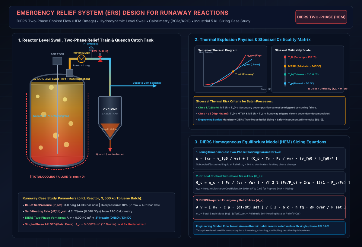
# 1. The Physics of Thermal Runaway in Batch Reactors
A thermal runaway is an autocatalytic feedback loop between chemical reaction kinetics and thermodynamics.
# A. Arrhenius Heat Generation ()
The chemical heat generation rate () follows an exponential Arrhenius temperature dependence:
Where:
- = Heat of reaction (exotherm) ( or )
- = Liquid reaction volume ()
- = Arrhenius pre-exponential frequency factor ( or )
- = Activation energy of the reaction ()
- = Universal gas constant ()
- = Absolute reactor temperature ()
- = Unreacted limiting reagent concentration ()
# B. Reactor Heat Removal ()
Conversely, the heat removal rate () through the reactor jacket or internal cooling coil is governed by Newton's Law of Cooling, exhibiting a linear temperature dependence:
Where:
- = Overall heat transfer coefficient ()
- = Wetted heat transfer surface area ()
- = Cooling utility temperature ()
Heat Rate (q)
^
|                                       / q_gen (Arrhenius Exponential)
|                                     /
|                                   /
|                                 /
|                 q_rem (Linear) / . . . . Unstable Runaway Regime (q_gen > q_rem)
|                     /        /
|                   /        /
|                 /   o   /  <- Critical Ignition Temperature (T_crit)
|               /   /
|             /  /  <- Stable Operating Point (q_gen = q_rem)
|           //
|         //
+--------------------------------------------------------->
                                                    Temperature (T)
# C. The Semenov Thermal Explosion Criterion
As long as and , the reactor maintains stable temperature control.
However, if temperature exceeds the Critical Ignition Temperature ()—or if cooling fails ()—exponential heat generation overwhelms linear heat dissipation. Self-heating accelerates rapidly:
# D. The Scale-Up Heat Transfer Deficit
In a 1 L laboratory flask, the available heat transfer surface area per unit volume () is approximately . When scaled up geometrically to a 5,000 L () industrial reactor, the ratio plummets to . A reaction that remains perfectly stable on the lab bench will rapidly runaway at commercial scale due to this massive loss in relative cooling capacity.
# 2. Reaction Hazard Screening & Calorimetric Data Generation
An emergency relief system cannot be engineered using thermodynamic handbook data alone. Precise experimental calorimetric testing is mandatory to quantify reaction kinetics, reagent accumulation, and secondary decomposition.
+-------------------------------------------------------------------------------+
|                    REACTION THERMAL HAZARD TESTING WORKFLOW                   |
+-------------------------------------------------------------------------------+
|                                                                               |
|  1. Differential Scanning Calorimetry (DSC)                                   |
|     - Onset Temperature of Decomposition (T_onset)                            |
|     - Total Decomposition Enthalpy (Delta-H_d in J/g)                         |
|                                                                               |
|                                 |                                             |
|                                 v                                             |
|                                                                               |
|  2. Reaction Calorimetry (RC1e / Simular / EasyMax)                          |
|     - True Synthesis Reaction Enthalpy (Delta-H_rxn)                          |
|     - Reagent Accumulation (X_accum) as function of dosing rate / temp        |
|     - Adiabatic Temperature Rise (Delta-T_ad = Delta-H_rxn / C_p)             |
|     - Maximum Temperature of Synthesis Reaction (MTSR)                        |
|                                                                               |
|                                 |                                             |
|                                 v                                             |
|                                                                               |
|  3. Accelerating Rate Calorimetry (ARC) / VSP2 (Adiabatic Testing)            |
|     - Secondary Decomposition Onset (T_D) under low thermal inertia (phi ~ 1) |
|     - Self-Heating Rate at Relief Setpoint: (dT/dt)_set                       |
|     - Pressure Generation Rate: (dP/dt)_set                                   |
|     - Time-to-Maximum-Rate under Adiabatic Conditions (TMR_ad)                |
|                                                                               |
+-------------------------------------------------------------------------------+
# Key Calorimetric Parameters:
- Adiabatic Temperature Rise of Synthesis ():
- Maximum Temperature of Synthesis Reaction ():
Where is normal process operating temperature, and is the unreacted fraction of limiting reagent accumulated in the batch during dosing.
3. Time to Maximum Rate ():
The time available from the loss of cooling until the self-heating runaway reaches its peak rate. For an -th order reaction:
# 3. The Stoessel Criticality Matrix
Francis Stoessel developed the definitive 5-class risk framework based on the relative ranking of four characteristic temperatures:
- = Normal Process Operating Temperature
- = Boiling Point of Reaction Solvent at Normal Operating Pressure
- = Maximum Temperature of Synthesis Reaction (Under Total Cooling Failure)
- = Onset Temperature of Secondary Exothermic Decomposition (from ARC with )
| Criticality Class | Temperature Relationship | Physical Mechanism & Thermal Risk | Mandatory Engineering Safeguards |
|---|---|---|---|
| Class 1 | Low hazard. Synthesis exotherm cannot trigger solvent boiling or secondary decomposition. | Standard cooling control; basic interlocks. | |
| Class 2 | Moderate hazard. Synthesis exotherm remains below solvent boiling and decomposition. | Emergency jacket cooling; high-temp feed trip. | |
| Class 3 | Solvent boils before decomposition. Reaction is tempered by solvent boiling. | High-capacity vapor condensation; DIERS vent sizing. | |
| Class 4 | HIGH HAZARD: Synthesis exotherm triggers violent secondary decomposition before solvent can boil to remove heat! | Fast-acting dump / quench tank; SIL-2 safety interlocks. | |
| Class 5 | EXTREME HAZARD: Solvent boiling occurs, but synthesis exotherm still drives temperature past decomposition onset . | Redundant DIERS two-phase ERS; dual rupture disks; quench. |
# 4. DIERS Classification of Runaway Systems
The Design Institute for Emergency Relief Systems (DIERS) classifies runaway chemical systems into three hydrodynamic categories based on the mechanism generating overpressure:
+----------------------------------------------------------------------------------------------------+
|                                    DIERS SYSTEM CLASSIFICATIONS                                    |
+------------------------------------+----------------------------------+----------------------------+
|        1. VAPOR SYSTEMS            |        2. GASSY SYSTEMS          |     3. HYBRID SYSTEMS      |
|      (Tempered Reactions)          |     (Non-Tempered Reactions)     |   (Boiling + Gas Gen)      |
+------------------------------------+----------------------------------+----------------------------+
| * Overpressure driven entirely by  | * Overpressure driven by rapid   | * Both volatile solvent    |
|   solvent vapor pressure.          |   generation of non-condensible  |   boiling and permanent    |
| * Heat generation is TEMPERED by   |   gases (N2, CO2, SO2, HCl).     |   gas generation occur     |
|   latent heat of boiling (h_fg).   | * ZERO latent heat cooling!      |   simultaneously.          |
| * Example: Alkylation in toluene,  | * Example: Diazonium couplings,  | * Example: Nitro reduction,|
|   Grignard formation in THF.       |   peroxide decompositions.       |   catalytic hydrogenation. |
+------------------------------------+----------------------------------+----------------------------+
# 5. Two-Phase Vapor-Liquid Flow & Hydrodynamic Level Swell
The foundational discovery of the DIERS project was that single-phase vapor venting equations (such as standard API 520 / ISO 4126) grossly undersize relief systems for runaway chemical reactors.
# Why Single-Phase Calculations Fail:
When a batch reactor undergoes a thermal runaway:
- Vapor and gas bubbles nucleate instantaneously throughout the entire liquid depth.
- The rapid upward transit of bubbles creates hydrodynamic level swell, converting the clear liquid into a churning, turbulent, frothy two-phase mixture.
- The swelling two-phase foam fills the entire vessel headspace ( void fraction expansion) and enters the relief nozzle as a dense two-phase vapor-liquid mixture.
    SINGLE-PHASE API 520 ASSUMPTION (FATAL)             ACTUAL DIERS TWO-PHASE REALITY
        +----------------------------+                    +----------------------------+
        |  Pure Vapor Discharge ==>  |                    | Two-Phase Liquid-Foam ==>  |
        | [\\\\\\\\ Headspace ////////] |                    | [oooo Churn-Turbulent oooo] |
        |                            |                    | [ooooooooooooooooooooooooo] |
        |~~~~~~~~~~~~~~~~~~~~~~~~~~~~|                    | [ooooooooooooooooooooooooo] |
        |                            |                    | [oooo 100% Level Swell ooo] |
        |     Clear Liquid Phase     |                    | [ooooooooooooooooooooooooo] |
        |                            |                    | [ooooooooooooooooooooooooo] |
        +----------------------------+                    +----------------------------+
      * Low fluid density (rho ~ 5 kg/m³)               * High fluid density (rho ~ 300-600 kg/m³)
      * High mass flux, small vent area                 * Massive mass flow penalty -> 4x-8x larger vent!
# The Mass Relief Penalty:
Because the density of a two-phase mixture () is than pure vapor (), discharging fluid through the vent nozzle requires a dramatically higher volumetric throughput. Sizing with single-phase vapor equations results in an undersized vent that cannot relieve the volumetric expansion, leading to vessel rupture.
# 6. DIERS Governing Sizing Equations (Leung -Method)
The Leung Omega () Parameter Method (Homogeneous Equilibrium Model - HEM) is the globally accepted standard for two-phase flashing flow relief sizing.
# Step 1: The Dimensionless Flashing Parameter ()
For a subcooled or saturated liquid at relief setpoint:
Where:
- = Leung dimensionless two-phase flashing parameter
- = Initial mass vapor quality ( for all-liquid initial relief)
- = Initial specific volume of liquid-vapor mixture ()
- = Specific volume difference between vapor and liquid (, )
- = Latent heat of vaporization of solvent at relief setpoint ()
- = Absolute relief pressure (, )
- = Absolute saturation temperature at relief pressure ()
- = Liquid specific heat capacity ()
# Step 2: Critical Choked Two-Phase Mass Flux ()
The critical mass flux discharged through the relief nozzle under choked flow conditions is:
Where:
- = Critical two-phase mass flux ()
- = Nozzle discharge coefficient ( for ASME certified safety valves; for rupture disk + relief piping system)
- = Critical pressure ratio, determined from:
- For (typical organic solvents):
# Step 3: Required Vent Area () for Vapor Systems (Fauske / DIERS Equation)
Where:
- = Required emergency relief vent area ()
- = Total reaction mass inside the vessel ()
- = Self-heating rate at the relief set pressure from adiabatic calorimetry ( or )
- = Allowable vessel overpressure (, typically to above setpoint per ASME Section VIII)
- = Relief set pressure absolute ()
# 7. Gassy System Relief Sizing (Non-Tempered Decomposition)
For gassy systems where pressure is generated by non-condensible gas generation rather than boiling:
Where is the peak volumetric gas generation rate per unit mass () measured directly in an adiabatic VSP2 / ARC test.
# 8. Emergency Relief Hardware Architecture
In pharmaceutical manufacturing, emergency relief systems must satisfy stringent containment, cleanability, and zero-leakage requirements:
                  +-------------------------------------------------------------+
                  |            DUAL RUPTURE DISK + SRV RELIEF TRAIN             |
                  +-------------------------------------------------------------+

                                            [ Safety Relief Valve (SRV) ]
                                            [ ASME Section VIII Full Lift]
                                                         |
                                                         +-- [ Pressure Transmitter (PT-101) ]
                                                         |   (Detects pinhole disk leaks)
                                            [ Rupture Disk Assembly ]
                                            [ Hastelloy C-22 Reverse Buckling ]
                                                         |
                                                         | (DN150 Relief Line)
                                                         |
                                            +-------------------------+
                                            |   5 KL BATCH REACTOR    |
                                            |   (ASME Design: 6 barg) |
                                            +-------------------------+
# Key Hardware Requirements:
- Reverse-Buckling Rupture Disk Upstream of Safety Relief Valve (SRV):
- Isolates the SRV from corrosive reaction vapors and crystalline polymer buildup.
- Eliminates fugitive VOC emissions through valve seats.
- Operates up to of rated burst pressure without metal fatigue.
- Tell-Tale Pressure Transmitter in Cavity:
- Mandated by ASME Section VIII Div 1 (UG-127). A pressure transmitter and excess flow valve mounted between disk and SRV alerts the DCS immediately if disk pinholes or bursts.
- Effluent Catch Tank & Knockout Drum:
- Vent lines must never discharge toxic solvents or energetic reagents directly to the atmosphere!
- Effluent is routed tangentially into a Cyclone Catch Tank designed to separate liquid hold-up, with vapors directed to a Vent Gas Scrubber or Thermal Oxidizer.
# 9. Comprehensive Worked Case Study: 5 KL Batch Reactor Runaway
# Process & Equipment Background:
- Reactor Tag: R-201 (Pharmaceutical Intermediate Nitration / Alkylation Reactor)
- Vessel Geometry: Nominal Volume (), Total Mass Charge
- Solvent / Carrier: Toluene ()
- Reactor Design Pressure: (Vessel MAWP)
- Relief Valve Set Pressure ():
- Allowable Overpressure (): overpressure ()
# Initiating Incident Scenario:
At reagent dosing, a plant-wide power outage causes total loss of cooling water + agitator trip. Reagent accumulates, triggering thermal runaway with secondary self-heating.
# Calorimetric & Physical Property Data (from ARC / RC1e):
- Reaction Self-Heating Rate at Setpoint:
- Solvent Boiling Point at :
- Latent Heat of Vaporization:
- Liquid Specific Heat:
- Liquid Specific Volume:
- Vapor Specific Volume at :
# Sizing Execution Step-by-Step:
# Step 1: Calculate Leung Flashing Parameter ()
Assuming all-liquid initial relief ():
# Step 2: Calculate Critical Pressure Ratio and Choked Mass Flux ()
For , the critical choked pressure ratio is:
Calculating choked two-phase mass flux with piping/disk discharge coefficient :
# Step 3: Compute DIERS Two-Phase Required Vent Area ()
Accounting for a safety margin of for friction losses in inlet/discharge piping and two-phase foaminess:
Solving for minimum nozzle inside diameter:
# Comparative Evaluation: Single-Phase vs. DIERS Two-Phase
| Calculation Methodology | Assumed Venting Phase | Calculated Area () | Minimum Required Nozzle | Plant Consequence if Installed |
|---|---|---|---|---|
| Traditional API 520 / 521 | Pure Single-Phase Vapor | 1-inch (DN25) | CATASTROPHIC FAILURE: Relieves only of volumetric swell; vessel ruptures at overpressure ! | |
| DIERS HEM Omega Method | Two-Phase Flashing Churn-Turbulent | 3-inch (DN80) / DN100 | SAFE CONTAINMENT: Restrains peak vessel pressure below ( overpressure limit). |
# 10. Safety Instrumented Systems (SIS/SIL-2) Layer of Protection
While an emergency relief system represents the final passive mechanical barrier, modern pharmaceutical process safety standards (IEC 61511 / ISA 84) mandate independent automated Safety Instrumented Functions (SIF) to prevent reaching relief setpoint:
[ Inherent Safety ] -> [ Basic Process Control (BPCS) ] -> [ Operator Alarm Intervention ]
                                                                     |
                                                                     v
[ Passive Mechanical ERS ] <- [ SIL-2 Safety Instrumented Interlock (SIF) ]
(Rupture Disk + PSV)           - High-High Temperature Trip (TT-101B >= 90 °C)
                               - Emergency Reagent Feed Cutoff (Fail-Closed)
                               - Automated Jacket Dump to Chilled Glycol (Fail-Open)
                               - Automatic Quench / Inhibitor Injection
# 11. Interactive Emergency Relief Vent Sizing Calculator
Need to calculate emergency vent area (), Leung Omega parameter (), critical mass flux (), and compare API 520 fire case vs. DIERS runaway reactions for your batch reactors?
Launch the Interactive Emergency Relief Vent Sizing Calculator →
Compute two-phase flashing flow relief areas, evaluate gassy vs. tempered systems, and generate process safety documentation for HAZOP and DIERS compliance.
# Applicable Engineering Standards & Codes Used
The engineering methodologies, design correlations, and safety criteria detailed in this article adhere to the following international standards and industry codes:
- OSHA 29 CFR 1910.119: Process Safety Management of Highly Hazardous Chemicals
- NFPA 654: Standard for the Prevention of Fire and Dust Explosions from Combustible Particulate Solids
- NFPA 68: Standard on Explosion Protection by Deflagration Venting
- NFPA 69: Standard on Explosion Prevention Systems
- ACGIH Industrial Ventilation: A Manual of Recommended Practice for Design (30th Edition): ACGIH Industrial Ventilation: A Manual of Recommended Practice for Design (30th Edition)
- ISO 28121: Industrial Ventilation and Dust Collection Systems Safety