# Design & Sizing of Acid Gas Scrubbers for Batch API Reactors: A Step-by-Step Engineering Guide
# Executive Summary & Industrial Context
In commercial Active Pharmaceutical Ingredient (API) and specialty chemical manufacturing, key synthetic transformations involve highly reactive chlorinating, sulfonating, and deprotecting reagents such as Phosphorus Oxychloride (), Thionyl Chloride (), Oxalyl Chloride, and Thiols. During batch processing, these reactions liberate large quantities of hazardous, corrosive acid gases—primarily Hydrogen Chloride (), Sulfur Dioxide (), Chlorine (), and Hydrogen Sulfide ().
Because batch reactions operate with time-varying addition rates and exothermic heat spikes, acid gas evolution is non-steady-state. If the scrubbing system is under-sized, sudden gas surges can over-pressurize reactor headspaces, blow out liquid seals, release toxic fumes into manufacturing bays, or exceed environmental emission limits ().
This engineering guide provides a rigorous blueprint for designing and sizing Wet Packed Acid Gas Scrubbers, covering gas generation stoichiometry, carrier gas dilution factors (), GPDC column diameter sizing, HTU/NTU mass transfer integration, exhaust blower static pressure calculations ( motor head baseline), recirculation pump hydraulics, and Heat of Neutralization Plate Heat Exchanger (PHE) & Cooling Tower Water Sizing.
# 1. System Anatomy of an Industrial Acid Gas Scrubber
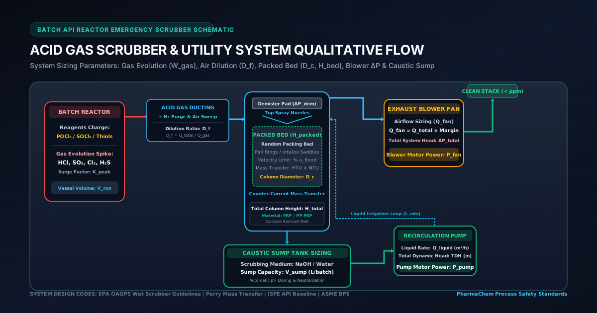
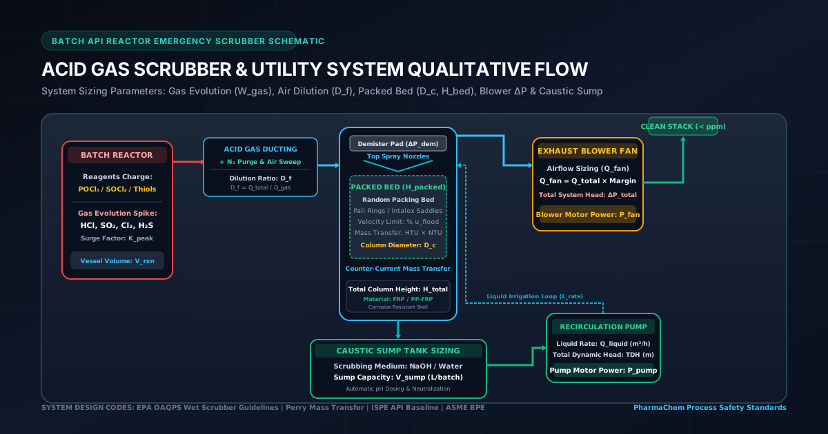
An industrial batch scrubber system consists of five primary interconnected unit operations:
  +-----------------------------------------------------------------------------------------+
  | BATCH REACTOR ACID GAS SCRUBBING SYSTEM SCHEMATIC                                       |
  +-----------------------------------------------------------------------------------------+
  |                                                                                         |
  |  [ Batch Reactor ] ──► Acid Gas Ducting ──► [ Packed Scrubbing Column ] ──► [ Blower ] ─► Stack
  |   (POCl3/SOCl2)       (with N2 Purge)         │ (Pall Rings / Saddles)    │ (Exhaust)   |
  |                                               ▼                           │             |
  |                                       [ Caustic Sump ] ◄──────────────────┘             |
  |                                       (10% NaOH Liquid) ──► [ Pump ] ──► [ PHE Cooler ]
  |                                                                               (CT Water)
  +-----------------------------------------------------------------------------------------+
- Reactor Vapor Ducting & Nitrogen Purge: Collects acid gas fumes and carrier gas ( or air in-leakage).
- Packed Absorption Column: Random plastic packing (Pall Rings or Intalox Saddles) providing gas-liquid interfacial area.
- Liquid Recirculation Sump & Neutralization: Stores circulating scrubbing solution ( caustic or water).
- Recirculation Pump & Titanium PHE Cooler: Delivers cooled scrubbing liquid to top spray distributors at a continuous irrigation rate () while removing neutralization heat via Cooling Tower Water.
- Exhaust Blower & Demister Pad: Maintains negative duct pressure and removes entrained liquid droplets prior to stack discharge.
# 2. Stoichiometric Gas Generation Rates & Peak Surge Factors ()
# 2.1 Reaction Stoichiometry Equations
The mass of acid gas liberated per batch depends on reactant stoichiometry:
- Chlorination:
- Thionyl Chloride Reaction:
- Thiol Deprotection:
# 2.2 Peak Acid Gas Mass Flow Rate ()
Because reagent addition is non-uniform, average gas evolution rate must be multiplied by a peak surge factor ():
# 3. Carrier Gas Dilution Factor () & Gas Concentration Analysis
# 3.1 Dilution Factor ()
In industrial fume extraction headers, carrier dilution air or purge gas () is introduced to sweep acid fumes from multiple reactor pick-up points. The Dilution Factor () is defined as:
Where:
- : Volumetric flow rate of pure acid gas liberated ()
- : Volumetric flow rate of carrier dilution air/nitrogen ()
- : Total combined gas flow rate entering scrubber ()
# 3.2 Volumetric & Mass Concentration %
The acid gas concentration in the entering gas stream is calculated as:
Safety Engineering Importance: Maintaining a minimum dilution factor () prevents localized high concentrations of flammable vapors (for solvent-containing fumes) and lowers acid dew point temperatures inside FRP ductwork.
# 4. Header Duct Sizing & Multi-Point Pick-up Velocity
Extraction ducting connecting reactor manholes to the scrubber header must maintain an economical gas velocity:
- Design Extraction Velocity (): (Recommended: ).
- Velocities below cause liquid droplet fallout.
- Velocities above create excessive noise and frictional static head drop.
# Duct Diameter Equation:
Standard nominal FRP/PP duct sizes are selected ().
# 5. Packed Column Diameter Sizing () & Flooding Optimisation
# 5.1 Sherwood-Leva-Eckert (GPDC) Correlation
Column diameter is governed by the gas flooding velocity (), calculated using the generalized pressure drop correlation:
Where:
- : Packing factor () (e.g. for 50mm PP Pall Rings)
- : Gas and liquid densities ()
- : Superficial flooding gas velocity ()
# 5.2 Target Flooding % vs Commercial Vessel Selection & Operating Flooding %
Design gas velocity is set at a user-selected Target Flooding % (typically , Max: ):
# Step-by-Step Commercial Sizing Example:
- For and :
- At 50% Target Flood: Standard Shell Selected = (Operating Flooding = 51.6%).
- At 60% Target Flood: Smart Economical Shell Selected = (Operating Flooding = 70.2%).
- At 70% Target Flood: Next Standard Shell = (Operating Flooding = 70.2%).
Key Takeaway: Both 60% and 70% target flooding map to the exact same commercial shell size, resulting in an identical safe operating flooding velocity of 70.2%!
# 6. Height of Packing () & Equivalent Multi-Column Criteria
# 6.1 HTU x NTU Mass Transfer Integration
Packed bed height () is calculated using the Transfer Unit method:
For absorption efficiency ():
Where for 50mm PP Pall Rings, yielding .
# 6.2 Industry Multi-Column Split Criteria ()
Adding sump () and distributor/demister space () gives a single column height .
- Single Column Limit: (Standard indoor API plant ceiling clearance).
- Scale Chem Industry Recommendation ():
- Install 2 Equivalent Columns in Series:
- Column 1 (Primary Bulk Scrubber): Takes of packed bed ( bed, total height). Absorbs acid.
- Column 2 (Polishing Scrubber): Takes remaining of packed bed ( bed, total height). Polishes emissions to .
- Install 2 Equivalent Columns in Series:
# 7. Exhaust Blower Motor Power Sizing (250 mmWC Static Baseline)
The exhaust blower must draw gas through ducting, packed beds, and demisters under negative pressure:
- Packed Bed Pressure Drop:
- System Pressure Drop:
- Motor Power Sizing Baseline ():
- While calculated system drop may be , chemical engineering best practice sizes the blower motor against a design static head to handle duct fouling and surge resistance.
# 8. Recirculation Pump Sizing & Liquid Distributor Velocity
# 8.1 Irrigation Rate & Pump Flow ()
To ensure thorough packing wetting, liquid irrigation rate is maintained at :
# 8.2 Spray Distributor Nozzle Velocity ()
Each spray nozzle orifice () is sized for an economical liquid discharge velocity of :
# 8.3 Pump Motor Power:
# 9. Caustic Neutralization Consumption Math
Neutralizer solution (, density ) consumption per batch is calculated stoichiometrically:
# 10. Heat of Neutralization () & Sump Recirculation PHE Cooler Sizing
# 10.1 Exothermic Heat Release Math ()
Gas-liquid absorption accompanied by chemical neutralization is strongly exothermic:
The heat generation rate () at peak gas evolution () is calculated as:
Adding a safety margin for sensible gas cooling yields total cooler duty:
# 10.2 Cooling Tower Water (CT Water) Flow Requirement ()
For a standard plant Cooling Tower Water loop ( supply return, ):
# 10.3 Recirculation Plate Heat Exchanger (PHE) Area ()
To prevent caustic sump overheating and loss of absorption efficiency, an inline Titanium Plate Heat Exchanger (PHE) is installed on the pump recirculation discharge line:
Where:
- (High-efficiency Titanium PHE plates for corrosive caustic vs CT water)
- Logarithmic Mean Temperature Difference
# Summary Sizing Table (Sample Batch API Case Study)
| Parameter | Sizing Result | Units | Industry Standard / Criterion |
|---|---|---|---|
| Acid Gas Species | / | - | From / Reaction |
| Peak Gas Evolution Rate | Surge Multiplier | ||
| Carrier Air Purge Flow | Dilution Factor | ||
| Main Header Duct Size | Sized @ velocity | ||
| Selected Shell Diameter | Smart Economical ( Op Flood) | ||
| Layout Recommendation | 2 Columns in Series | - | Single height ceiling limit |
| Blower Motor Rating | Sized @ motor head | ||
| Recirculation Pump Rating | Mag-Drive Pump ( TDH) | ||
| Neutralization Heat Duty | Exothermic heat of neutralization | ||
| CT Water Requirement | Cooling Water loop | ||
| Titanium PHE Area | Titanium Plate Heat Exchanger | ||
| Caustic Demand | solution demand |