# CIP/SIP Design: Why Most Systems Fail Validation and How to Prevent It
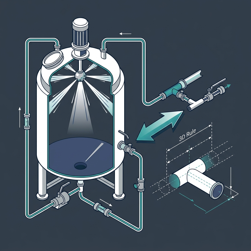
Sanitary engineering dictates that Clean-in-Place (CIP) and Steam-in-Place (SIP) systems must be designed to completely clean and sterilize product-contact surfaces. Poor system designs lead to validation failure, batch contamination, and product recalls.
In this guide, we review the dynamic flow rules, spray ball coverage validation, and dead-leg rules using metric units.
# 1. CIP Cleanability Sizing Rules (Metric)
- CIP Turbulent Flow Velocity: To provide sufficient wall shear stress to remove biofilms, the rinse fluid must flow at a minimum velocity of 1.5 m/s in all piping lines. This ensures a turbulent flow regime with a Reynolds Number (Re) greater than 10,000.
- Vessel Spray Ball Flow Rate: Standard static spray balls require a rinse water feed rate of 60 to 90 Liters/min per meter of vessel perimeter (L/min/m) for vertical walls, and 10 L/min per nozzle for horizontal equipment.
- Dead-Leg Limits (ASME BPE): The stagnant pipe branch length (L) relative to the internal tube diameter (D) must comply with the ratio: L/D <= 2. This prevents stagnant zones where cleaning fluids cannot circulate.
# 2. Worked Example: CIP Loop Flow Sizing
Size the CIP flow rate for a 50 mm internal diameter sanitary transfer tube to achieve the required 1.5 m/s shear velocity.
# Step 1: Calculate Cross-Sectional Area (A)
A = pi * (D ^ 2) / 4 = 3.1416 * (0.05 ^ 2) / 4 = 0.001963 sq m
# Step 2: Calculate Volumetric Flow Rate (Q)
Q = Velocity * Area = 1.5 m/s * 0.001963 sq m = 0.002945 m^3/s
Q = 0.002945 * 3600 = 10.6 m^3/h = 176.7 Liters/min
Therefore, the CIP supply pump must deliver at least 177 L/min at the terminal pressure to validate the cleaning loop velocity.
# 3. Reference Standards
- ASME BPE Standard: Part SD (Sanitary Design) and Part SG (Sealing Components).
- ISPE Baseline Guide Volume 4: Water and Steam Systems.
# Applicable Engineering Standards & Codes Used
The engineering methodologies, design correlations, and safety criteria detailed in this article adhere to the following international standards and industry codes:
- ASME B31.3: Process Piping Code
- API RP 14E: Recommended Practice for Design and Installation of Offshore Production Platform Piping Systems
- Hydraulic Institute Standards (HI 1.3, HI 2.3) for Centrifugal and Positive Displacement Pumps: Hydraulic Institute Standards (HI 1.3, HI 2.3) for Centrifugal and Positive Displacement Pumps
- ISO 5167: Measurement of Fluid Flow by Means of Pressure Differential Devices