# Catalytic Hydrogenation Reactor Engineering & Gas-Liquid Mass Transfer (kLa, Buss Loop & Autoclaves)
# 3-Phase Gas-Liquid-Solid Dynamics, Hydrogen Uptake Rates (HUR), Hatta Numbers, and Pyrophoric Catalyst Safety
Catalytic hydrogenation—reducing nitro groups, aromatic rings, alkenes, carbonyls, and nitriles using heterogeneous precious metal catalysts (Pd/C, Pt/C, Raney Nickel)—is one of the most widely executed transformations in API synthesis.
However, scaling catalytic hydrogenation is notoriously complex: gaseous hydrogen has negligible solubility in organic solvents (), reaction heats are violently exothermic (), and dry catalyst powders ignite spontaneously in air.
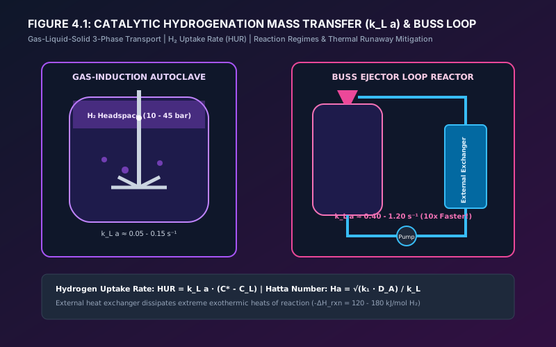
# 1. The 3-Phase Mass Transfer Pathway & Resistances in Series
In a heterogeneous slurry reactor, gaseous hydrogen must navigate multiple physical resistance steps to reach active catalytic sites:
               THE 5-STEP 3-PHASE HYDROGEN MASS TRANSFER CASCADE
  [ H2 Gas Bubble ]
         │
         ▼ (1) Gas-Film Diffusion & Dissolution (k_L a)
  [ Gas-Liquid Interface ]
         │
         ▼ (2) Bulk Liquid Convective Transport
  [ Bulk Organic Solvent (C_L) ]
         │
         ▼ (3) Liquid-Solid Boundary Layer Diffusion (k_s a_p)
  [ External Catalyst Particle Surface ]
         │
         ▼ (4) Intraparticle Pore Diffusion (Knudsen / Effective D_eff)
  [ Metal Crystallite Active Site (Pd / Pt / Ni) ]
         │
         ▼ (5) Surface Adsorption & Chemical Reaction
  [ Hydrogenated Product Molecules Desorption ]
# 1.1. Overall Rate Equation
The overall volumetric rate of hydrogen consumption is given by resistances in series:
Where:
- : Volumetric gas-liquid mass transfer coefficient ().
- : Saturation solubility of in solvent via Henry's Law ().
- : Liquid-solid external mass transfer coefficient ().
- : Internal catalyst effectiveness factor ().
- : Catalyst concentration ().
# 2. Diagnostic Hatta Number (Ha) & Reaction Regimes
Chemical engineers diagnose the rate-limiting step using the dimensionless Hatta Number ():
                           HYDROGENATION REACTION REGIMES
  Ha < 0.3                      0.3 <= Ha <= 3.0                   Ha > 3.0
 ◄─────────────────────────────┼──────────────────────────────────┼────────────────────────►
  Regime 1: Slow Kinetics      Regime 2: Mixed Control            Regime 3: Pure Mass Transfer
  Liquid is saturated (C_L≈C*) Combined diffusion and kinetics.   All H2 consumed at interface.
  Agitation has no effect.     Scale-up depends on both.          Speed & k_L a dictate rate.
- Regime 1 (): True chemical kinetic control. Increasing agitation RPM or gas recirculation has zero effect on the conversion rate.
- Regime 3 (): Severe gas-liquid mass transfer limitation. The bulk liquid is starved of hydrogen (). In this regime, the reaction rate scales linearly with power input () and .
# 3. Reactor Architectures: Batch Autoclaves vs. Buss Loop vs. Continuous Flow Hydrogenators
                       THE THREE HYDROGENATION REACTOR PARADIGMS
    (A) Hollow-Shaft Autoclave           (B) Buss Ejector Loop                (C) Continuous Flow Hydrogenator
   ┌──────────────────────────┐        ┌──────────────────────────┐        ┌──────────────────────────────────┐
   │ H2 Headspace             │        │ Reaction Autoclave Tank  │        │ Liquid Feed + H2 Gas             │
   │      │ (Suction ports)   │        │      │                   │        │      │ (Mass flow controllers)   │
   │      ▼                   │        │      ▼ (Slurry)          │        │      ▼                           │
   │ Hollow Rotating Shaft    │        │ High-Head Slurry Pump    │        │ Continuous Trickle Bed /         │
   │      │                   │        │      │                   │        │ Taylor Flow Microchannel Column  │
   │      ▼                   │        │      ▼                   │        │ (Stationary Pellet / Slurry)     │
   │ Self-Aspirating Rotor    │        │ External Heat Exchanger  │        │      │ (Residence time: 1-5 min) │
   │ (Fine gas dispersion)    │        │      │                   │        │      ▼                           │
   │                          │        │      ▼                   │        │ In-Line Gas-Liquid Separator     │
   │ Batch Volume: 1-10 kL    │        │ Supersonic Jet Ejector   │        │ (Zero Catalyst Filtration!)      │
   └──────────────────────────┘        └──────────────────────────┘        └──────────────────────────────────┘
| Performance Parameter | Conventional Sparged Autoclave | Gas-Inducing Hollow Shaft Autoclave | Buss Ejector Loop Reactor | Continuous Flow Hydrogenator (Fixed-Bed / Microchannel) |
|---|---|---|---|---|
| Volumetric Mass Transfer () | (Extraordinary) | |||
| Reaction Residence / Cycle Time | ||||
| Active Reacting Hold-up Volume | ( hazard reduction) | |||
| Maximum Operating Pressure | (Effortless in small tubes) | |||
| Specific Heat Transfer Area () | (Ext. HEX) | (Isothermal) | ||
| Catalyst Handling & Filtration | Batch manual/candle filter | Batch candle filter | Batch candle filter | None (Fixed-Bed stays in tube for months) |
| Thermal Runaway Risk | Extreme ( energy stored) | High ( energy stored) | Moderate (Pump trip shuts loop) | Inherently Safe (Instantaneous fuel ) |
| Chemo-Selectivity (Over-reduction) | Poor to Moderate (CSTR backmixing) | Moderate | Good | Superior (Strict Plug-Flow ) |
# 3.1. Continuous Flow Hydrogenation: Physics of Taylor Flow & Packed Beds
Continuous flow hydrogenation achieves unprecedented process intensification via two primary mechanical embodiments:
# 1. Packed-Bed Tubular Flow (Trickle-Bed Catalytic Reactors)
Stationary pellets or extrudates of heterogeneous catalyst ( Pd, Pt, or Ru on alumina, carbon, or silica) are packed into high-pressure tubular columns ( ID).
- Liquid substrate and hydrogen gas flow co-currently downward over the packing.
- As the liquid trickles as a thin dynamic film over the catalyst grains, the liquid-solid diffusion distance is reduced to a few microns, driving above .
- The Operational Breakthrough: Because the catalyst remains permanently immobilized in the bed, downstream catalyst filtration, cake washing, and pyrophoric sludge handling are completely eliminated. The hydrogenated effluent exits the reactor as crystal-clear solution.
# 2. Gas-Liquid Taylor Slug Flow in Microchannels
When hydrogen gas and substrate solution are co-fed through a micro- or meso-scale channel (), surface tension segments the mixture into alternating gas bubbles and liquid slugs (Taylor flow):
- As the liquid slug travels down the channel, viscous shear against the tube wall drives intense internal recirculating vortices (toroidal counter-rotating flow).
- These vortices continuously replenish fresh, hydrogen-rich liquid from the gas-bubble interface directly to the channel core and suspended nano-catalyst particles:
- Under Taylor flow, gas-liquid mass transfer rates exceed , allowing reactions that require 12 hours in a stirred tank to reach 100% conversion in 90 seconds!
# 4. Comprehensive Worked Case Study: Sizing a 3,000 L Nitro-Reduction
# Problem Statement:
An aromatic nitro intermediate () is reduced to its corresponding amine () in Methanol using Pd/C catalyst ( wet with water):
- Batch charge: ().
- Total slurry volume: ().
- Reaction stoichiometry: .
- Heat of reaction: ().
- Operating temperature: at ().
- Desired cycle time: .
# Step 1: Hydrogen Consumption & Volumetric Uptake Rate
- Total required:
- Standard Gas Volume (STP ):
- Average Hydrogen Uptake Rate:
# Step 2: Heat Removal & Thermal Sizing
- Total heat generated:
- Average thermal heat duty:
- Peak thermal duty (assuming 1.6x kinetic peaking factor during initial zero-order period):
# Step 3: Required Cooling Area
- Cooling water supply: , return .
- Reactor temperature: .
- .
- SS316L vessel jacket overall .
- Required heat transfer area:
- Standard vessel () provides approximately wetted jacket area. Therefore, supplementary internal helical immersion coils () or external circulation cooling must be installed to prevent thermal runaway.
# Step 4: The Paradigm Shift — Sizing the Same Nitro-Reduction in a Continuous Flow Hydrogenator
To illustrate why modern pharmaceutical development is rapidly transitioning to continuous manufacturing, consider running the exact same chemical transformation ( nitro compound in methanol) through a Continuous Fixed-Bed Trickle-Flow Reactor:
                 BATCH AUTOCLAVE vs. CONTINUOUS FLOW HYDROGENATOR
  Parameter                            3,000 L Batch Autoclave           Continuous Trickle-Bed Reactor
 ──────────────────────────────────────────────────────────────────────────────────────────────────────
  Active Reacting Liquid Hold-Up      2,500 Liters                      10.4 Liters (Over 8h shift)
  Catalyst State                      5% Pd/C Slurry (45 kg wet cake)   Stationary Extrudates in Tube
  Required Operating Pressure         15 bar g                          50 bar g (Effortless in tube)
  Volumetric Mass Transfer (k_L a)    0.12 s⁻¹                          2.80 s⁻¹ (23x Higher!)
  Reaction Residence Time             3.0 Hours (180 min)               2.0 Minutes (120 seconds)
  Specific Heat Area (A/V)            3.7 m²/m³ (Severe limit)          1,200 m²/m³ (Ultra-isothermal)
  Maximum Stored Runaway Energy       1,328 MegaJoules (Bomb risk!)     < 15 MegaJoules (Inherently Safe)
  Downstream Catalyst Filtration      Mandatory (Closed Candle Filter)  NONE (Product exits crystal clear)
# Engineering Calculation:
- Flow Rate & Reactor Sizing (8-Hour Shift Production):
- Feed throughput: .
- Elevating pressure to increases solubility by , collapsing required residence time to .
- Required Active Reactor Volume ():
- A skid with four schedule 80 jacketed pipes ( length each, packed with Pd/Al2O3 catalyst pellets) completely replaces the massive autoclave!
- Inherent Process Safety (Zero Catastrophic Runaway Potential):
- In the autoclave, of boiling, flammable methanol containing of nitro compound ( heat of reaction) is primed for thermal explosion if cooling water or agitation fails.
- In the continuous reactor, only of nitro compound ( of reaction energy) is present in the reactor at any millisecond. If emergency shutdown occurs, closing the feed valve de-energizes the reaction instantly.
- Eliminating the Pyrophoric Nightmare:
- Because the catalyst remains packed in the tube, operators never touch pyrophoric Pd/C powder during campaigns. After 6 to 12 months of continuous production, the catalyst cartridge is safely deactivated in-situ and returned to the refiner for precious metal reclamation.
# 5. Catalyst Handling, Pyrophoricity & Process Safety
# Applicable Engineering Standards & Codes Used
- ASME BPVC Section VIII, Division 1 & Division 2: Design of High-Pressure Hydrogen Autoclaves.
- API 520 / 521: Sizing and Installation of Pressure-Relief Devices in Refineries and Chemical Plants.
- NFPA 68 / 69: Deflagration Venting and Explosion Prevention Systems.
- IEC 60079-10-1: Explosive Atmospheres: Classification of Hazardous Areas (Hydrogen Gas Group IIC).
- ISO 4126: Safety Devices for Protection Against Excessive Pressure.