# Batch Reactor Agitator Design: Impeller Selection, Power, Mixing, Scale-Up, and Engineering Correlations
In chemical synthesis and Active Pharmaceutical Ingredient (API) manufacturing, a batch reactor agitator is far more than a simple electric motor driving a rotating shaft.
It is the primary transport phenomena engine that dictates the rate of species blending, turbulent energy dissipation, boundary-layer heat removal, solid-liquid dissolution, and gas-liquid interfacial mass transfer across the entire vessel.
A poorly designed or improperly scaled agitation system does not merely cause extended batch cycle times—it leads to uncontrolled temperature hot-spots, localized selectivity degradation, secondary byproduct formation, severe crystal attrition, un-suspended catalyst dead zones, and catastrophic mechanical shaft failure.
The central engineering question this technical guide addresses is:
How do process, project, and equipment design engineers select, calculate, size, and scale an agitator for a batch reactor so that required mixing performance is achieved seamlessly from laboratory (1 L) to pilot (100 L) and commercial scale (5 KL to 10 KL)?
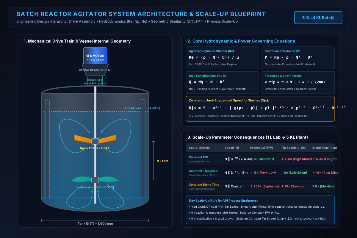
# 1. Introduction: Why Agitator Design Matters
In an industrial batch reactor, an agitator must accomplish multiple concurrent physical and chemical objectives across different reaction steps:
- Homogeneous Blending: Rapidly dispersing miscible liquid feeds to avoid localized stoichiometry excesses.
- Thermal Uniformity & Heat Transfer: Sweeping liquid past jacketed vessel walls and internal baffles to maximize process-side heat transfer coefficients ().
- Solids Suspension & Dissolution: Maintaining heterogeneous catalysts (e.g., 5% Pd/C) or raw material crystals in a fully off-bottom suspended state.
- Gas-Liquid Dispersion: Shearing sparged gases into micro-bubbles and recirculating the headspace gas to maximize interfacial area () and overall volumetric mass transfer ().
- Liquid-Liquid Emulsification: Shearing immiscible organic-aqueous phases into stable droplets during phase-transfer catalysis or extractive workups.
- Controlled Crystallization: Providing gentle bulk circulation while keeping maximum shear rates low enough to prevent crystal attrition and uncontrolled secondary nucleation.
An impeller assembly perfectly optimized for low-viscosity solvent blending (e.g., high-speed hydrofoil) will fail completely when tasked with circulating a pseudoplastic, shear-thinning polymer slurry or dispersing high-flow hydrogen gas. Agitator design must always begin with the fundamental mixing process objective.
# 2. What Exactly Does an Agitator Need to Achieve?
Before specifying motor kilowatts or selecting impeller geometries, the process engineer must classify the dominant hydrodynamic duty:
| Mixing Objective | Primary Fluid Dynamic Requirement | Key Governing Metric | Critical Engineering Hazard of Undersizing |
|---|---|---|---|
| Miscible Liquid Blending | High bulk volumetric pumping capacity (). | Blend Time () | Localized pH/concentration spikes, unreacted reagent pockets. |
| Heat-Transfer Enhancement | High fluid shear and boundary layer disruption at vessel wall. | Nusselt Number (), Inside Film Coefficient () | Thermal runaway, wall fouling, severe batch cooling delays. |
| Solid-Liquid Suspension | Axial off-bottom upward velocity exceeding particle settling velocity (). | Just-Suspended Speed ( via Zwietering) | Catalyst settling, incomplete conversion, localized hot spots. |
| Gas-Liquid Mass Transfer | High turbulent shear near sparger; gas bubble breakup. | Volumetric Mass Transfer Coefficient (), Gassed Power () | Gas flooding, severe reaction rate starvation (Ha > 3). |
| Liquid-Liquid Dispersion | Micro-scale turbulent eddy dissipation (). | Sauter Mean Droplet Diameter (), Weber Number () | Phase separation, low interfacial reaction rate. |
| Controlled Crystallization | Uniform bulk suspension with minimal maximum tip shear (). | Tip Speed (), Power/Volume () | Crystal breakage, fines generation, clogged filter dryers (ANFD). |
# 3. Basic Components of a Reactor Agitation System
A standard top-entry batch reactor agitation system comprises seven integrated mechanical components:
- Electric Drive Motor: Standard 4-pole or 6-pole TEFC / Flameproof (Ex-d) induction motor, operated through a Variable Frequency Drive (VFD) for precision speed modulation.
- Speed Reduction Gearbox: High-efficiency helical or bevel-helical gearbox providing fixed torque multiplication (typical ratios to ).
- Flexible / Rigid Coupling: Connects the gearbox output shaft to the agitator drive shaft, absorbing minor angular and parallel misalignments.
- Mechanical Seal Assembly: Double-acting, pressurized liquid-lubricated or dry-gas mechanical seal with a barrier fluid reservoir (operating at above maximum reactor operating pressure) to ensure hermetic containment.
- Agitator Shaft: Solid or heavy-wall tubular stainless steel (SS316L, Hastelloy C-22, Alloy 59) cantilevered shaft designed for combined torsional shear and cyclic bending stresses.
- Impeller Stages: Single or multi-stage hubs with bolted or welded blades positioned at calibrated liquid heights.
- Vessel Baffles: Fully welded or removable vertical wall baffles that convert rotational liquid swirl into vertical axial circulation loops.
# Mounting Configurations:
- Top-Entry Agitator (Dominant in Pharma/API): Cantilevered shaft entering through the top dome nozzle. Allows easy maintenance, clean-in-place (CIP), and eliminates leak paths below the liquid level.
- Bottom-Entry Agitator: Common in bioprocessing fermenters and sterile magnetic-drive mixing tanks. Requires low headroom but presents seal reliability risks in abrasive chemical slurries.
- Side-Entry Agitator: Used almost exclusively in large petroleum and bulk storage tanks; unsuited for batch API synthesis reactors.
# 4. Important Reactor Geometry Parameters
Geometric similarity forms the mathematical foundation of chemical agitation and scale-up. The primary dimensions of an agitated vertical cylindrical vessel with a standard dished bottom are:
- = Vessel Inside Diameter (m)
- = Liquid Charge Height from bottom tangent line (m)
- = Impeller Swept Outer Diameter (m)
- = Impeller Bottom Clearance from lowest point of dish (m)
- = Radial Baffle Width (m)
- = Inter-Impeller Axial Spacing in multi-tier assemblies (m)
- = Solid Agitator Shaft Diameter (m)
# Standard Geometric Starting Ratios:
| Dimension Ratio | Standard Range | Recommended Baseline | Physical Significance |
|---|---|---|---|
| (Impeller-to-Tank Ratio) | (Axial) / (Radial) | Balances shear rate vs. bulk volumetric circulation flow. | |
| (Aspect Ratio) | Standard dished batch reactor envelope; requires dual impellers. | ||
| (Bottom Clearance Ratio) | Optimum off-bottom solid suspension and dish sweeping. | ||
| (Baffle Width Ratio) | () | Standard 4-baffle fully baffled condition; suppresses vortexing. | |
| (Baffle-to-Wall Gap) | () | Prevents solid particle stagnation and dead-zone accumulation behind baffles. | |
| (Dual Impeller Spacing) | Prevents hydrodynamic flow interference between adjacent stages. |
# 5. Impeller Types: Fluid Mechanics & Selection Matrix
Impellers are classified by their primary discharge vector into Axial-Flow, Radial-Flow, and Close-Clearance (High-Viscosity) designs:
| Impeller Family | Specific Geometry | Primary Flow Vector | Power Number () | Pumping Number () | Operating Viscosity Range (mPa·s) | Primary Industrial Application |
|---|---|---|---|---|---|---|
| High-Efficiency Hydrofoil | HE-3, A310, Maxflo | Pure Axial (Downward) | Low-shear blending, rapid circulation, low-power solids suspension. | |||
| Pitched-Blade Turbine (PBT) | 4-Blade 45° Pitch | Mixed (Axial + Radial) | General synthesis, solid-liquid dissolution, crystallization, heat transfer. | |||
| Marine Propeller | 3-Blade True Pitch | Pure Axial | Small pilot vessels, high-speed portable mixers, bench autoclaves. | |||
| Rushton Disk Turbine (RDT) | 6 Flat Blades on Disk | Pure Radial | Gas-liquid dispersion, hydrogenation, liquid-liquid high-shear emulsification. | |||
| Curved-Blade Radial | Smith (CD-6), Concave | Pure Radial | High-rate gas dispersion; resists gas cavity flooding better than Rushton. | |||
| Anchor Agitator | Contour Wall Scraper | Tangential / Laminar | High-viscosity resin synthesis, cooling crystallization wall heat transfer. | |||
| Helical Ribbon | Single/Double Flight | Top-to-Bottom Axial | Polymers, creams, high-density pseudoplastic pastes in laminar regime. |
# 6. Axial vs. Radial Flow Hydrodynamics
Understanding the physical flow field generated by an impeller is essential for selecting the correct geometry:
# A. Axial-Flow Impellers (PBT, Hydrofoil, Propeller)
- Fluid Motion: Fluid is propelled parallel to the agitator shaft toward the bottom dish, sweeps across the lower vessel head, travels upward along the outer baffled wall, and returns to the impeller eye.
- Hydrodynamic Characteristic: Generates maximum volumetric liquid turnover () per unit of motor power consumed ().
- Primary Utility: Blending of miscible fluids, solids suspension, and general heat-transfer circulation.
# B. Radial-Flow Impellers (Rushton Turbine, Flat Blade)
- Fluid Motion: Fluid is discharged radially outward perpendicular to the shaft toward the vessel wall, where it splits into two distinct circulation loops: one moving upward toward the surface, and one moving downward toward the dish.
- Hydrodynamic Characteristic: Generates high localized shear rates and turbulent energy dissipation () in the impeller discharge stream, but exhibits lower bulk circulation efficiency.
- Primary Utility: Breaking up sparged gas bubbles, dispersing immiscible liquid droplets, and high-intensity gas-liquid mass transfer.
# 7. Reynolds Number for Agitated Vessels
Fluid flow inside an agitated reactor is governed by the Impeller Reynolds Number ():
Where:
- = Impeller Reynolds Number (Dimensionless)
- = Process fluid density ()
- = Impeller rotational speed in revolutions per second ( or ) [Note: ]
- = Impeller outer diameter (m)
- = Dynamic fluid viscosity ( or ) [Note: ]
# Hydrodynamic Flow Regimes in Agitated Vessels:
- Laminar Regime (): Viscous forces dominate. Fluid motion occurs solely along streamlines; zero turbulence. Power consumption is directly proportional to viscosity and independent of density ().
- Transitional Regime (): Both inertial and viscous forces interact. Complex vortex structures form near blade tips while bulk fluid exhibits laminar decay.
- Fully Turbulent Regime (): Inertial forces completely dominate. The boundary layer is fully turbulent; Power Number () reaches an asymptotic constant value independent of fluid viscosity ().
# 8. The Impeller Power Number ()
The Power Number () (also known as the Newton Number) is the fundamental dimensionless drag coefficient representing an impeller's resistance to rotational fluid motion:
Rearranging to solve for required shaft power demand ():
Where:
- = Net shaft power delivered to fluid (Watts, or )
- = Turbulent Impeller Power Number (Dimensionless)
- = Liquid density ()
- = Agitator rotational speed ()
- = Impeller outer diameter (m)
Critical Scaling Principle: In the turbulent regime, power escalates with the 3rd power of speed () and the 5th power of diameter ()! A mere increase in impeller diameter at constant RPM increases required power by ( increase)!
# 9. The Impeller Power Curve ( vs. )
Agitator equipment manufacturers provide empirical vs. Power Curves calibrated for specific impeller blade profiles, hub angles, and vessel baffle configurations:
- Laminar Zone (): , where is a laminar shape factor ( for PBT, for anchors).
- Turbulent Zone (): becomes constant ( for HE-3 Hydrofoil; for standard 4-blade 45° PBT; for Rushton Turbine).
# 10. The Pumping Number () and Bulk Flow Rate
The Pumping Number () quantifies the volumetric liquid discharge rate pumped by the impeller per revolution:
Rearranging to solve for total impeller discharge capacity ():
Where:
- = Primary volumetric pumping rate discharged from impeller blades ()
- = Impeller Pumping Number (Dimensionless, typically )
- = Rotational speed ()
- = Impeller diameter (m)
# Flow-to-Power Efficiency Metric:
To evaluate how efficiently an impeller generates bulk fluid turnover per kilowatt consumed, engineers evaluate the Pumping Efficiency Ratio ():
High-efficiency hydrofoils maximize the ratio (), delivering over 5 times more bulk pumping turnover per kilowatt than a pitched blade turbine () or Rushton turbine ().
# 11. Power per Unit Volume ()
Power per Unit Volume () is the most widely cited process engineering metric for reactor agitation intensity:
Where:
- = Volumetric power input ( or )
- = Total agitated liquid volume ()
# Standard Industrial Design Benchmarks:
- Mild Blending & Storage (): Equalizing bulk temperature in solvent storage tanks.
- Moderate Chemical Synthesis (): Standard single-phase homogeneous reactions, dissolving soluble salts.
- Intense Reaction & Dissolution (): Viscous slurries, competitive fast reactions, high-rate heat transfer.
- Extreme Gas-Liquid & Hydrogenation (): High-pressure 3-phase hydrogenations, aerobic fermentations.
# 12. Impeller Tip Speed () and Shear Rates
The Impeller Tip Speed () represents the maximum linear peripheral velocity of the outer blade edge:
Where:
- = Impeller peripheral tip speed ()
- = Impeller outer diameter (m)
- = Rotational speed ()
# Maximum vs. Average Shear Rates:
The maximum fluid shear rate occurs directly in the narrow trailing vortex zone at the blade tip:
Where for flat blades and for hydrofoils.
The Crystallization Shear Limit: In API crystallization, exceeding a critical tip speed () shatters fragile crystal facets, generating massive populations of sub-10 micron fines that blind centrifuge filter bags and increase ANFD drying times by .
# 13. Agitator Shaft Torque ()
Torque is the mechanical rotational force transmitted from the drive motor and gearbox down the shaft to overcome liquid drag:
Where:
- = Shaft torque (Newton-meters, )
- = Shaft power (Watts, )
- = Rotational speed ()
# Operating Torque vs. Starting Torque:
During cold startup or re-suspension of settled solids after a power failure, the Starting Torque can reach of nominal steady-state operating torque. Gearboxes and solid shafts must be mechanically rated against peak starting torque.
# 14. Motor Power Selection & Mechanical Drive Sizing
The nameplate electrical motor rating () must always exceed the net shaft process power () to account for mechanical transmission losses and process viscosity variations:
Where:
- = Gearbox mechanical transmission efficiency (typically for premium helical drives).
- = Mechanical seal drag efficiency (typically ; seal friction absorbs depending on shaft diameter and barrier fluid pressure).
- = Electric motor electrical efficiency (typically for IE3/IE4 premium efficiency motors).
- = Project Engineering Service Factor (typically for standard liquids; for slurry/polymer reactions).
# 15. Blend Time and Mixing Kinetics ()
Mixing Time () is the time required after a tracer injection to achieve chemical composition homogeneity across all points in the vessel:
In the fully turbulent regime (), the dimensionless product of rotational speed and mixing time () is an invariant geometric constant:
For a standard 4-blade pitched-blade turbine (, fully baffled):
Therefore, at (120 RPM):
# 16. General Empirical Blending Correlations
For vessels operating in the turbulent regime (), Grenville (1992) and Nienow established the generalized blending correlation for 95% homogeneity:
Solving directly for blend time ():
Substituting the turbulent power relationship into the equation:
Expressing this in terms of volumetric power dissipation () where (for ):
Key Process Lesson & Scale-Up Penalty:
- Blending time scales inversely with the cube root of power per unit volume (). Doubling the motor power reduces mixing time by only (a modest reduction).
- On scale-up at constant , blend time is NOT constant—it increases with the vessel scale as ! Scaling from a 100 L pilot vessel () to a 10 KL commercial reactor () increases blend time by -fold!
# 17. Vessel Baffles and Vortex Suppression
Operating an unbaffled vertical reactor with a centered top-entry agitator in low-viscosity liquid creates a massive central rotational vortex.
- Unbaffled Systems: Fluid rotates as a solid-body centrifuge. Vertical top-to-bottom circulation collapses; power draw drops by up to ; central vortex draws air/nitrogen into the liquid, causing severe frothing and shaft whipping.
- Fully Baffled Systems: Vertical wall baffles intercept circular flow vectors, redirecting energy into powerful axial turnover loops and maximizing motor power transfer into turbulent micro-mixing.
# Standard Stainless Steel (Metallic) Baffle Rules:
- Standard Baffle Count: 4 vertical wall baffles spaced at 90° intervals around the internal circumference.
- Standard Baffle Width: (for general synthesis) or (for high-efficiency hydrofoils).
- Wall Offset Clearance: Baffles must be stood off from the vessel shell by (or ) to prevent solids accumulation and promote self-cleaning during CIP.
# Glass-Lined Reactors (GLR) Baffle Configurations:
In Glass-Lined Steel Reactors (GLRs)—ubiquitous in acidic and corrosive API synthesis—internal wall baffles cannot be welded to the vessel shell because the glass coating would crack under thermal and mechanical stress. Instead, GLRs utilize top-nozzle-suspended designs:
- Beaver-Tail (D-Type) Baffles: Flattened oval cross-section baffles suspended from top dome nozzles, positioned close to the agitator swept path. Typically 1 or 2 beaver-tail baffles are installed.
- Finger / Dip-Pipe Baffles: Multi-purpose tubular probes that combine vortex suppression with thermowells (housing dual Pt-100 RTDs) and sampling dip tubes.
- Hydrodynamics in GLRs: Because 1 or 2 beaver-tail baffles provide partial baffling ( multiplier compared to 4 full wall baffles), hydraulic side forces () on the shaft increase by , requiring heavier shaft diameters and stiffer drive lanterns.
- Cryo-Lock & Retreat Curve Impellers (RCI): Standard in GLRs, featuring swept-back blades designed to be assembled through the vessel top manway and locked cryogenically onto the shaft without damaging the glass lining.
# 18. Multi-Stage Impeller Assemblies
When the liquid depth-to-tank diameter ratio exceeds , a single impeller cannot establish complete top-to-bottom circulation, creating isolated stagnant zones in the upper liquid layer.
# Design Criteria for Dual-Impeller Systems:
- Lower Impeller (): High-efficiency downward axial hydrofoil or PBT to sweep the dished bottom head.
- Upper Impeller (Submerged below surface): Downward axial PBT or hydrofoil to draw fresh liquid feeds downward into the core.
- Axial Spacing (): Must be maintained between . Spacing causes flow coupling where both stages act as a single inefficient thick impeller; spacing splits the fluid into two disconnected circulation loops with zero inter-stage exchange.
# 19. Solid-Liquid Suspension & The Zwietering Correlation
For heterogeneous catalytic reactions (e.g., hydrogenation using Pd/C, Raney Nickel) or dissolving solid API crystal feeds, the agitator must operate at or above the Just-Suspended Speed (), defined as the minimum rotational speed at which no solid particle remains stationary on the vessel bottom for longer than 1 to 2 seconds (ASTM / Zwietering 1-second criterion).
# The Zwietering Fundamental Equation:
Where:
- = Just-suspended impeller speed ()
- = Dimensionless Zwietering geometry constant (function of impeller type, , and )
- = Kinematic viscosity of liquid ()
- = Gravitational acceleration ()
- = Solid particle density ()
- = Liquid carrier density ()
- = Mean solid particle diameter (m)
- = Solids mass concentration ratio (, )
- = Impeller diameter (m)
# Zwietering Constant () Reference Values ( Clearance, Fully Baffled):
- High-Efficiency Hydrofoil (A310 / HE-3):
- 4-Blade Pitched Blade Turbine (45°):
- 6-Blade Rushton Radial Turbine: (Very inefficient for solids suspension)
# 20. Gas-Liquid Agitation, Mass Transfer (), and Gassed Power
In gas-liquid reactions (e.g., catalytic hydrogenation, oxidation, halogenation), the chemical reaction rate is governed by the volumetric gas-liquid mass transfer rate ():
# The Van't Riet Correlation for Coalescing Organic Systems:
Where:
- = Volumetric mass transfer coefficient ()
- = Gassed power per unit volume ()
- = Superficial gas velocity through the vessel cross section ()
# The Gassed Power Drop ():
When gas is sparged beneath an impeller, low-density gas cavities form behind the blades, reducing the effective density and drag. The Gassed Power () drops to of the Ungassed Power ().
Severe Design Trap: If gas supply trips during a live commercial reaction, the agitator immediately transitions from gassed to ungassed conditions. If the drive motor was sized strictly for gassed power (), the sudden jump to ungassed power () will trip the motor on electrical overload! Always size drive motors for 100% ungassed liquid power.
# Sparger Design, Location & Gas Flooding Prevention:
- Sparger Configuration: In clean pharmaceutical reactors, use a Ring Sparger with downward-facing discharge holes () to prevent catalyst powder accumulation inside the sparger tube.
- Sparger Diameter & Standoff: Ring sparger diameter should be , positioned at an axial standoff distance of directly beneath the lower radial/concave turbine.
- Preventing Impeller Flooding: If the gas flow rate is excessive relative to impeller speed, gas cavities engulf the blades, the pumping action collapses, and gas bubbles shoot upward in a central plume without radial dispersion (Impeller Flooding). The minimum impeller speed to avoid flooding is evaluated using the Gas Flow Number () and Froude Number ():
Operating above this critical speed ensures the impeller remains in the loaded, fully dispersed regime.
# 21. Agitation Effects on Reactor Heat Transfer
In jacketed synthesis reactors, agitation directly governs the Inside Process-Side Heat Transfer Film Coefficient ():
# Generalized Nusselt Correlation for Agitated Jacketed Vessels:
Where:
- = Nusselt Number (Dimensionless)
- = Prandtl Number of fluid ()
- = Thermal conductivity of fluid ()
- = Fluid viscosity at vessel wall temperature
- = Empirical heat transfer constant ( for PBT; for Rushton turbines; for anchors in laminar regime)
# 22. Agitator Design for High-Viscosity Systems
When fluid viscosity rises above (e.g., polymerizations, concentrated API slurries, fermentation broths), conventional open turbines fail completely because turbulent kinetic energy decays within millimeters of the blade tip, creating an isolated rotating liquid cylinder (the "cavern effect") surrounded by stagnant fluid.
# Close-Clearance Impeller Dynamics:
- Anchor Agitators: Clearance from vessel wall (). Sweeps viscous boundary layers off the cooled jacket wall, preventing thermal scorching.
- Helical Ribbon Agitators: Double-flight helical ribbons physically lift fluid up the vessel wall and pump it down the center core, enforcing positive turnover even at .
# 23. Scale-Up of Batch Reactor Agitators: The 6 Governing Criteria
When scaling an agitation system from lab/pilot () to commercial scale (), process engineers must select a single primary governing scale-up criterion:
| Scale-Up Criterion | Mathematical Governing Rule | Scale Exponent () | Typical Industrial Application |
|---|---|---|---|
| 1. Constant Power / Volume () | Mass-transfer limited synthesis, fast competitive reactions. | ||
| 2. Constant Tip Speed () | Shear-sensitive crystallization, mammalian cell culture. | ||
| 3. Constant Blend Time () | () | Unrealistic in large plants; causes explosive power demand! | |
| 4. Constant Reynolds Number () | Strictly hydrodynamic study; impractical for mass transfer. | ||
| 5. Constant Solids Suspension () | (Zwietering) | Slurry dissolving, heterogeneous catalyst suspension. | |
| 6. Constant Mass Transfer () | Hydrogenation, gas-liquid sparged reactions. |
# 24. Why RPM Should Never Be Scaled Directly
Consider scaling a process from a laboratory reactor () running at to a commercial reactor (, scale factor ):
- If scaling directly on Constant RPM ():
The power requirement explodes by over 160,000-fold, destroying the shaft and motor!
- If scaling on Constant Power per Unit Volume ():
The commercial agitator operates at , achieving identical volumetric power input.
- If scaling on Constant Tip Speed ():
# 25. Complete Multi-Scale Scale-Up Comparison Table
The following table demonstrates the hydrodynamic shift across five geometrically similar vessel scales (, , , , ) scaled on Constant Power per Volume ():
| Parameter | Lab Scale (1 L) | Bench Scale (100 L) | Pilot Scale (1 KL) | Plant Scale (5 KL) | Production Scale (10 KL) |
|---|---|---|---|---|---|
| Working Volume () | |||||
| Vessel Diameter () | |||||
| Impeller Diameter () | |||||
| Agitator Speed () | |||||
| Net Shaft Power () | |||||
| Power/Volume () | |||||
| Tip Speed () | |||||
| Reynolds Number () | |||||
| Blend Time () | |||||
| Shaft Torque () |
# 26. Practical Engineering Worked Example: Sizing a 5 KL Batch Reactor
# Process Design Input Data:
- Vessel Nominal Volume: ()
- Operating Working Batch Volume: ()
- Process Fluid Density:
- Process Fluid Dynamic Viscosity:
- Target Mixing Intensity: Moderate Chemical Synthesis ()
# Step 1: Establish Vessel Geometry
- Choosing standard aspect ratio :
- Liquid height:
- Impeller Diameter (): ()
# Step 2: Select Impeller Geometry & Power Number
- Dual Impeller Selection: Lower 4-Blade PBT (), Upper 3-Blade Hydrofoil ().
- Combined Assembly Power Number:
# Step 3: Calculate Required Rotational Speed ()
- Target total shaft power:
- Solving for :
# Step 4: Verify Hydrodynamic Regimes & Safety Checks
- Reynolds Number:
- Impeller Tip Speed:
- Shaft Operating Torque:
# Step 5: Motor & Gearbox Rating
- Applying mechanical efficiencies () and Service Factor :
- Selected Commercial Standard Motor: (10 HP), 4-Pole (1440 RPM nominal), 415V / 50 Hz, Ex-d Flameproof
- Gearbox Reduction Ratio: Ratio (Helical Bevel Geared Unit)
# 27. Shaft Mechanical Design, ASME Code Sizing & Critical Speed Dynamics
A top-entry batch reactor agitator shaft operates as an extended, vertical overhung cantilever beam. It is subjected to simultaneous, complex mechanical stresses:
- Continuous Torsional Shear Stress (): Transmitted from the electric motor and gearbox down the shaft to overcome fluid drag.
- Cyclic Reverse Bending Stress (): Induced by dynamic, asymmetric fluid hydraulic side loads () acting on the rotating impeller blades as they pass near baffles or liquid level interfaces.
- Axial Tensile / Compressive Stress: From impeller weight and hydraulic down-thrust/up-thrust forces.
# A. ASME Code Governing Equations for Solid Shaft Diameter ()
Under the ASME Code for Design of Transmission Shafting (incorporating Guest's Maximum Shear Stress Theory and Rankine's Maximum Normal Stress Theory), the minimum solid shaft diameter is sized from the Equivalent Combined Torsional Moment ():
The minimum required solid shaft diameter () is calculated as:
Where:
- = Transmitted operating torque ():
- = Hydraulic lateral side force acting at the lowest impeller ():
(where is the dimensionless hydraulic side-load factor: for single-phase liquid blending; for gas dispersion, liquid level draw-down, or solid suspension)
- = Maximum bending moment at the lower support bearing ():
(where is the total overhung length from the lower support bearing to the lowest impeller hub)
- = Combined shock and fatigue factor for bending ( for rotating shafts with minor to heavy shock)
- = Combined shock and fatigue factor for torsion ()
- = Maximum allowable shear stress for the shaft material ( or ):
(For standard annealed SS316L: ; for Hastelloy C-22: )
# B. Deflection Limits at the Mechanical Seal & Impeller Tip
Excessive shaft deflection is the #1 root cause of premature mechanical seal failure and batch contamination in pharmaceutical reactors:
- Deflection at the Mechanical Seal Face ():
(where is the distance from the lower support bearing to the seal faces, and )
2. Deflection at the Lowest Impeller Tip ():
# C. Critical Whirling Speed () & Resonance Avoidance
A cantilevered agitator shaft possesses natural lateral vibration frequencies. If the operating rotational speed () coincides with a natural frequency, violent shaft whirling / resonance occurs:
Using the Rayleigh-Ritz Method for Overhung Shafts with Concentrated Impeller Masses:
Where is the total static lateral deflection under gravitational and concentrated blade loads:
- Rigid Shaft Design (Sub-Critical — Mandatory for Top-Entry Pharma Reactors):
- Flexible Shaft Design (Super-Critical):
# D. Comprehensive Worked Case Study: Minimum Shaft Diameter Sizing for a 5 KL Commercial Batch Reactor
# Design Problem Statement:
Size the minimum solid shaft diameter, evaluate operating torque, bending moments, seal face deflections, and verify critical speed resonance for a 5,000 L () Pharmaceutical Synthesis Reactor (R-101).
# Input Design Specifications:
- Working Batch Volume (): ()
- Liquid Density (): , Viscosity
- Dual-Impeller Assembly: Lower 4-Blade PBT () + Upper PBT (), Total Blade Mass
- Operating Speed (): ()
- Total Absorbed Process Power (): ()
- Overhung Shaft Length (): (distance from lower bearing in drive lantern to bottom impeller)
- Seal Face Location (): () below lower support bearing in compact drive lantern
- Shaft Material of Construction: Forged SS316L (, , )
- ASME Safety Factors: Shock factor , Fatigue factor , Hydraulic side factor , Design Safety Factor
# Step-by-Step Calculation:
# Step 1: Calculate Transmitted Operating Torque ()
Applying the design safety factor ( for starting load):
# Step 2: Calculate Fluid Hydraulic Lateral Side Load ()
Acting at the lower impeller radius ():
# Step 3: Calculate Maximum Bending Moment at Lower Support Bearing ()
# Step 4: Calculate ASME Equivalent Combined Torsional Moment ()
# Step 5: Determine Minimum Required Solid Shaft Diameter ()
Using allowable shear stress for SS316L ():
- Commercial Standard Metric Shaft Diameters: 65 mm, 70 mm, 75 mm, 80 mm, 90 mm, 100 mm.
- Selected Standard Shaft Diameter: Select () solid precision-ground bar stock.
# Step 6: Verify Deflection at Mechanical Seal Faces ()
For :
Deflection at seal position ():
Mechanical Seal Check: maximum allowable limit (and meets API 682 criterion). PASSED!
Design Takeaway: Locating the lower support bearing close to the seal faces () is critical. If were , deflection would escalate to (), causing rapid seal face wear and batch leakage. Alternatively, process engineers utilize the dedicated Reactor Shaft Mechanical Sizing Calculator to evaluate multi-impeller loads, hollow shafts, and deflection-governed sizing.
# Step 7: Verify First Critical Whirling Speed () & Resonance
- Bare shaft volume & mass:
- Effective vibrating mass:
- Static gravitational deflection ():
- First critical whirling speed ():
- Operating speed ratio:
Dynamic Whirling Check: Operating speed is of critical speed, well below the rigid-shaft ceiling. The shaft will run with zero resonance, zero harmonic whipping, and maximum bearing life.
# 28. Agitator Mechanical Seal Design
A reactor mechanical seal operates under far harsher conditions than a pump seal due to long shaft overhang, dynamic shaft runout (), vapor-phase operation, and thermal cycling.
# Mechanical Seal Architecture:
- Double Pressurized Liquid-Lubricated Seal (Standard): Employs dual back-to-back or face-to-face silicon carbide / carbon seal faces with a dedicated Thermosiphon Barrier Fluid Pot (operating with white oil, propylene glycol, or compatible solvent at overpressure).
- Dry-Running Non-Contacting Gas Seal: Uses nitrogen gas barrier film; ideal for ultra-pure API synthesis where zero barrier fluid contamination is tolerated.
# 29. API Process Impeller Selection Decision Matrix
| Process Operation | Recommended Impeller Configuration | Target Range | Critical Scale-Up Governing Rule |
|---|---|---|---|
| Fast Homogeneous Liquid Reaction | Dual Pitched Blade Turbines () | Constant Power per Unit Volume () | |
| High-Pressure Gas Hydrogenation | Gas-Induction / Cavity-Dispersion Radial | Constant and Superficial Gas Velocity () | |
| Shear-Sensitive Crystallization | Low-Shear High-Efficiency Axial Hydrofoil | Constant Tip Speed () | |
| Dense Slurry Catalyst Suspension | Wide-Blade Hydrofoil or Downward PBT | Zwietering Just-Suspended Speed () | |
| High-Viscosity Polymerization () | Double-Flight Helical Ribbon / Anchor | Bulk Wall Turnover & Shear-Thinning Dynamics |
# 30. 15 Common Agitator Design Mistakes in Plant Scale-Up
- Selecting the Motor Before Sizing the Impeller: Buying a 10 HP motor based on catalogue guessing rather than calculating net shaft power from .
- Treating RPM as an Absolute Mixing Metric: Believing 100 RPM provides the same mixing across 100 L and 10 KL reactors.
- Ignoring Viscosity & Reynolds Regime: Applying turbulent power numbers () to viscous transitional or laminar slurries.
- Direct RPM Linear Scale-Up: Scaling RPM directly (), which causes power to explode by .
- Assuming Constant Is Universally Applicable: Using constant for crystallization scale-up, causing severe crystal attrition and filter blinding.
- Operating Unbaffled Vessels: Leaving a reactor unbaffled in turbulent liquid, resulting in solid-body swirl, zero axial turnover, and a vortex drawing air into the pump suction.
- Ignoring Gassed vs. Ungassed Power Shift: Sizing motor strictly for gassed conditions; motor trips when gas is stopped during liquid priming.
- Neglecting Mechanical Seal Barrier Pressure: Running barrier fluid pressure lower than reactor internal pressure, forcing toxic reaction vapor into the seal faces.
- Operating in the Critical Speed Resonance Band (): Causing catastrophic shaft whipping, bearing failure, and shattered seal faces.
- Inadequate Inter-Impeller Spacing (): Squeezing dual impellers too close together, destroying hydrodynamic efficiency.
- Using Single-Zone Agitators in High Aspect Ratio Vessels (): Leaving stagnant unmixed fluid in the upper third of the vessel.
- Ignoring Starting Torque: Selecting an undersized gearbox that shears gears when restarting an agitator submerged in settled solids.
- Ignoring Non-Newtonian Rheology: Assuming pseudoplastic or thixotropic slurries behave like water.
- Over-Agitating Crystallizations: Believing higher power always improves product; destroys crystal size distribution (CSD).
- Accepting Generic Vendor Guarantees: Accepting "this 5 KL agitator is standard" without verifying fluid properties, , and requirements.
# 31. Standard Agitator Design Calculation Sheet
When generating process data sheets for equipment fabrication, process engineers must complete the following standard specification sheet:
================================================================================
          PHARMACEUTICAL BATCH REACTOR AGITATOR PROCESS DATASHEET
================================================================================
PROJECT / VESSEL TAG: R-101 (5 KL API Batch Synthesis Reactor)
--------------------------------------------------------------------------------
1. PROCESS OPERATING DATA:
   - Working Batch Volume (V):           4.0 m³ (4,000 L)
   - Operating Liquid Density (ρ):       920 kg/m³
   - Operating Dynamic Viscosity (μ):    2.4 cP (0.0024 Pa·s)
   - Design Operating Temperature:       -20 °C to +140 °C
   - Design Operating Pressure:          Full Vacuum to +6.0 barg
   - Solids Content / Particle Size:     5.0 wt% Pd/C Catalyst / 35 µm

2. VESSEL INTERNAL GEOMETRY:
   - Tank Inside Diameter (T):           1,600 mm
   - Total Liquid Height (H):            1,890 mm (Aspect Ratio H/T = 1.18)
   - Bottom Head Geometry:               ASME Torispherical Dish Head
   - Baffles:                            4 Vertical Baffles, Width B = 160 mm (T/10)
   - Baffle Wall Clearance (B_gap):      32 mm (T/50)

3. AGITATOR MECHANICAL SPECIFICATION:
   - Mounting Type:                      Top-Entry Centered Cantilever
   - Lower Impeller:                     4-Blade Pitched Blade Turbine (45°), D1 = 560 mm
   - Upper Impeller:                     3-Blade High-Efficiency Hydrofoil, D2 = 560 mm
   - Bottom Clearance (C):               480 mm (C/T = 0.30)
   - Inter-Impeller Spacing (S):         700 mm (S/D = 1.25)
   - Impeller Assembly Power No (Np):    1.65 (Turbulent)
   - Impeller Pumping Number (Nq):       0.82

4. HYDRODYNAMIC CALCULATION SUMMARY:
   - Operating Agitator Speed (N):       218 RPM (3.63 rev/s) [VFD: 50 to 250 RPM]
   - Impeller Reynolds Number (Re):      4.36 × 10⁵ (Fully Turbulent)
   - Net Shaft Power Demand (P):         4.00 kW (5.36 HP)
   - Power per Unit Volume (P/V):        1.00 kW/m³
   - Impeller Tip Speed (v_tip):         6.39 m/s
   - Nominal Operating Torque (Tq):      175.4 N·m
   - 95% Blending Time (t_95):           22.1 seconds
   - Zwietering Njs for Pd/C:            88 RPM (Operating 218 RPM >> Njs = Full Suspension)

5. DRIVE & TRANSMISSION SPECIFICATION:
   - Electric Motor Rating:              7.5 kW (10 HP), 4-Pole, 415V/50Hz, Flameproof Ex-d
   - Gearbox Type & Ratio:               Helical-Bevel Unit, Ratio = 1:6.6
   - Overhung Shaft Length (L):          1,800 mm (from lower bearing to bottom hub)
   - Solid Shaft Diameter (ds):          65 mm (SS316L Solid Forging)
   - First Critical Speed (N_crit):      410 RPM (Operating speed 218 RPM <= 0.53 N_crit)
   - Mechanical Seal:                    Double Balanced Cartridge Seal, Pressurized Barrier Pot
================================================================================
# 32. Vendor Data Verification Checklist
When reviewing bids from agitator vendors, process engineers must reject generic catalog statements ("This agitator fits a 5 KL reactor") and demand the following verified engineering deliverables:
- Certified Impeller Power & Pumping Curves ( and vs. ): Verified across the vessel's specific , , and baffle geometry.
- Finite Element Shaft Deflection & Stress Analysis: Showing combined von Mises stresses allowable fatigue limits under peak starting torque.
- Modal Critical Speed Calculation Report: Proving first lateral natural frequency .
- Mechanical Seal Thermal Balance & Barrier Fluid Plan: Certifying barrier fluid flow rate and seal face temperature rise under full vacuum and maximum steam jacket temperatures.
# 33. The 11-Step Agitator Design Hierarchy
The systematic process engineering design workflow must always proceed sequentially through the following hierarchy:
[1. Process Objective Defined] (Blending, Solids, Heat Transfer, Gas-Liquid, Crystallization)
              |
              v
[2. Fluid Physical Properties] (Density, Viscosity Rheology, Solids Density/Size, Gas Flow)
              |
              v
[3. Vessel Geometry Established] (Tank Diameter T, Liquid Height H, Head Profile)
              |
              v
[4. Impeller Family Selected] (Axial Hydrofoil, Pitched Blade, Radial Rushton, High-Visc Ribbon)
              |
              v
[5. Geometric Ratios Fixed] (D/T = 0.33, C/T = 0.30, S/D = 1.25, Baffles B = T/10)
              |
              v
[6. Flow Regime & Reynolds Number Calculated] (Re = rho * N * D^2 / mu)
              |
              v
[7. Power Number & Power Demand Computed] (P = Np * rho * N^3 * D^5)
              |
              v
[8. Hydrodynamic Validation] (P/V, Tip Speed v_tip, Blend Time t_mix, Zwietering Njs)
              |
              v
[9. Scale-Up Protocol Selected] (Constant P/V, Tip Speed, or Njs)
              |
              v
[10. Shaft Mechanical & Dynamic Sizing] (Combined Torque/Bending, Diameter ds, Critical Speed Ncrit)
              |
              v
[11. Motor, Gearbox & Seal System Integrated] (Service Factor Fs >= 1.3, Double Mechanical Seal)
# 34. Core Engineering Conclusion
Agitator design is not about selecting a motor size or arbitrarily assigning an RPM from previous plant recipes.
It is about precisely tailoring three-dimensional fluid motion, shear distribution, and turbulent energy dissipation to satisfy the chemical and physical transport requirements of the process.
The most efficient agitator is never the one with the highest horsepower motor. It is the system that delivers the exact required process performance with the optimum balance of bulk volumetric circulation, localized shear, thermal boundary layer disruption, and multi-decade mechanical reliability.
# 35. Interactive Batch Reactor Engineering Calculators
Need to calculate power demand (), Reynolds number (), torque (), tip speed (), or size agitator shafts for your chemical or API reactor? Utilize our interactive web tools:
Launch the Interactive Batch Reactor Scale-Up Calculator →
Compute impeller power numbers, motor kilowatts, blend times, and multi-scale scale-up trajectories across laboratory, pilot, and commercial batch reactors.Launch the Reactor Shaft Mechanical Sizing Calculator →
Calculate ASME equivalent torsional moments (), dynamic bending moments, API 682 seal radial runout (), hollow vs solid shafts, and first critical whirling speeds ().
# Applicable Engineering Standards & Codes Used
The engineering methodologies, design correlations, and safety criteria detailed in this article adhere to the following international standards and industry codes:
- DIN 28131: Agitators for Process Vessels — Terms, Nomenclature and Main Geometric Dimensions.
- DIN 28161: Agitator Shafts — Technical Delivery Conditions and Mechanical Stress Sizing.
- ASME B106.1M: Design of Transmission Shafting (Combined Torsion, Bending Fatigue, and Allowable Shear Stresses).
- API 682 / ISO 21049: Shaft Sealing Systems for Rotary Equipment (Mechanical Seal Radial Deflection and Barrier Fluid Circuits).
- ASME Boiler and Pressure Vessel Code (BPVC) Section VIII Division 1 & 2: Rules for Construction of Pressure Vessels and Jacketed Reaction Vessels.
- ASME BPE (Bioprocessing Equipment): cGMP Surface Finish Requirements (, Electropolished), Sanitary Drainability, and Material Certifications.
- ISO 1940-1: Mechanical Vibration — Balance Quality Requirements for Rotors (Dynamic Balancing to Grade G2.5 / G6.3).
- ATEX Directive 2014/34/EU & IECEx / NFPA 70: Hazardous Area Classification and Flameproof (Ex-d) Electric Drive Systems for Zone 1 / Class I Div 1 Environments.