# Aspen Plus for Pharma & Chemical Engineers: 10 Essential Models & Areas of Utilization
# Executive Summary & Engineering Scope
In commodity chemical engineering (such as petroleum refining), process simulation is dominated by continuous steady-state gas and hydrocarbon flows. In contrast, pharmaceutical and specialty chemical manufacturing is dominated by batch unit operations, solids handling, highly non-ideal organic solvent mixtures, electrolyte active salts, and environmental utility systems.
Aspen Plus (along with Aspen Batch Process Developer and Aspen Dynamics) is the industry-standard process simulator for modeling, optimizing, and scaling up chemical and API synthesis trains.
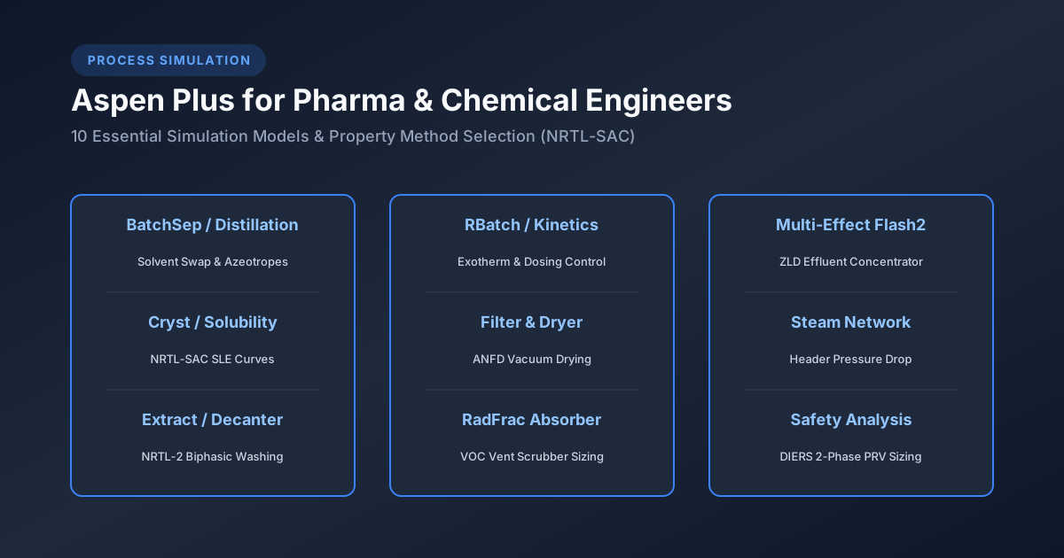
This practical guide details 10 essential Aspen Plus simulation models and key areas of plant utilization every chemical and process engineer should master:
- Model 1: Solvent Swap & Azeotropic Batch Distillation (
BatchSep/RadFrac) - Model 2: Solid-Liquid Crystallization & Solubility Curve (
Cryst/Flash3) - Model 3: Liquid-Liquid Extraction & Biphasic Wash Cuts (
Extract/Decanter) - Model 4: Batch Agitated Reactor Kinetics & Exotherm (
RBatch/RCSTR) - Model 5: Vacuum Filtration & Cake Drying (
Filter/Dryer) - Model 6: VOC Solvent Recovery & Vent Scrubber Sizing (
RadFracAbsorber) - Model 7: Bioreactor & Enzyme Kinetic Modeling (
RCSTR/ Biological Reactions) - Model 8: Multi-Effect Evaporator & Zero Liquid Discharge (ZLD) Concentrator (
Flash2) - Model 9: Plant Utility Network & Steam System Balancing (
Heater/Pipeline) - Model 10: Emergency Relief System (ERS) Two-Phase Flashing (
Safety Analysis)
Each model section includes a step-by-step tutorial on how to set up, configure, and solve the model in Aspen Plus.
# 1. Selecting the Correct Property Method in Aspen Plus
Before placing any block on the flowsheet, selecting the correct thermodynamic Property Method is the most critical step in Aspen Plus. Using an incorrect property model (such as PENG-ROB or IDEAL) for polar pharmaceutical solvents causes massive simulation errors!
                  ┌──────────────────────────────────────────────────────────┐
                  │          ASPEN PLUS PROPERTY METHOD SELECTION            │
                  └────────────────────────────┬─────────────────────────────┘
                                               │
           ┌───────────────────────────────────┴───────────────────────────────────┐
           ▼                                                                       ▼
┌──────────────────────────────────────────┐                            ┌──────────────────────────────────────────┐
│      POLAR ORGANIC SOLVENT MIXTURES      │                            │      API SOLIDS & ELECTROLYTE SALTS      │
├──────────────────────────────────────────┤                            ├──────────────────────────────────────────┤
│ • NRTL / NRTL-2 (Binary VLE / LLE)       │                            │ • NRTL-SAC (Segment Activity Coeff)      │
│ • UNIQUAC / UNIFAC (Predictive)          │                            │ • ELECNRTL (Electrolyte NRTL)            │
│ • COSMO-SAC (Quantum Chemical)           │                            │ • SOLIDS / ENTHALPY (Solid Properties)   │
└──────────────────────────────────────────┘                            └──────────────────────────────────────────┘
| Pharma Process Domain | Recommended Property Method | Physical Justification & Application |
|---|---|---|
| Organic Solvent Mixtures (VLE / LLE) | NRTL / NRTL-2 | Accurate liquid activity coefficients () for non-ideal, azeotropic solvent pairs (e.g., Ethanol-Toluene, Acetone-Water). |
| API Solubility & Route Screening | NRTL-SAC | Predicts solid API solubility in pure and mixed solvent systems using molecular segment descriptors (Hydrophobic, Polar, Hydrogen Donor/Acceptor). |
| Electrolyte & Acid-Base Salts | ELECNRTL | Account for ionic dissociation, osmotic coefficients, and salt precipitation ( control, crystallization). |
| Predictive Vapor-Liquid Equilibrium | UNIFAC / UNIFAC-DMD | Group-contribution method used when experimental binary interaction parameters () are unavailable. |
| Polymers & Amorphous Solids | PC-SAFT | Models polymer-solvent phase behavior, glass transition temperatures, and solid-state solubility. |
# 2. Model 1: Solvent Swap & Azeotropic Batch Distillation (`BatchSep`)
# A. Process Challenge
API synthesis frequently requires swapping a reaction solvent (e.g., low-boiling Methanol, ) for a crystallization solvent (e.g., high-boiling Toluene, ). This is performed in a jacketed reactor equipped with an overhead batch column (BatchSep).
                ┌─────────────────────────────────────────────────────────┐
                │          MODEL 1: SOLVENT SWAP BATCHSEP FLOWSHEET       │
                └────────────────────────────┬────────────────────────────┘
                                             │
      Overhead Vapor ──► [ Condenser ] ──► [ Reflux Splitter ] ──► Distillate Receiver
                                                                 (Methanol Top Cut)
                                 ▲
                                 │ Column Riser
                                 │
  Fresh Toluene Charge ──► [ BATCH REACTOR HEEL ] (Methanol + Toluene + API Solid)
# B. Step-by-Step Instructions: How to Solve in Aspen Plus
Step 1: Setup Components & Property Method
- Open Aspen Plus Create a Blank Simulation.
- In
ComponentsSpecifications, addMETHANOL,TOLUENE, andWATER. - In
PropertiesSpecifications, selectNRTLas the primary property method. - Click
ParametersBinary InteractionNRTL-1to verify parameters exist for Methanol-Toluene.
Step 2: Place
BatchSepBlock on Flowsheet- Go to
SimulationenvironmentColumnstab DragBatchSeponto the workspace. - Attach feed stream
FEEDand distillate outlet streamDISTILL.
- Go to
Step 3: Define Reactor Initial Charge (Pot Hold-Up)
- Double-click
BatchSepblockPot Chargetab. - Specify initial liquid charge: (, ).
- Set initial pot pressure: ().
- Double-click
Step 4: Configure Column Geometry & Internals
- Go to
Configurationtab Specify . - Set Condenser Type:
Total Condenser. - Set Stage 1 (Condenser) holdup: ; Column internal tray holdup: .
- Go to
Step 5: Define Operating Steps (Batch Distillation Protocol)
- Click
Operating Stepstab Create Step 1 (Heat-Up):- Operating Spec:
Reboiler Heat Duty = 100 kWuntilPot Temperature = 65°C(Boiling begins).
- Operating Spec:
- Create Step 2 (Constant Reflux Ratio):
- Operating Spec:
Reflux Ratio = 4.0,Reboiler Heat Duty = 100 kW. - Stop Condition:
Methanol mole fraction in pot <= 0.02(98% Methanol removed).
- Operating Spec:
- Create Step 3 (Fed-Batch Solvent Dosing):
- Add continuous fresh Toluene feed at into pot while boiling to maintain constant liquid volume.
- Click
Step 6: Run & Analyze Results
- Click
Control PanelPress F5 (Run). - View
ResultsProfilesto display the composition vs time curve:- Methanol mole fraction in distillate remains during top cut, then drops.
- Final pot composition confirms residual Methanol in Toluene.
- Click
# 3. Model 2: Solid-Liquid Crystallization & Solubility (`Cryst`)
# A. Process Challenge
Crystallization dictates API crystal size distribution (CSD), polymorphism, and filtration performance. The engineer must model the temperature-dependent solubility curve and calculate solid yield upon cooling.
# B. Step-by-Step Instructions: How to Solve in Aspen Plus
Step 1: Define Solids Component Category
- In
ComponentsSpecifications, add target API molecule (e.g.,PARACETAMOL). - Change Component Type from
ConventionaltoSolid(orC-Solid). - Input solid thermophysical properties: Solid Heat Capacity (), Heat of Fusion (), and Melting Point ().
- In
Step 2: Property Method & Solubility Regression (
NRTL-SAC)- Select
NRTL-SACproperty method. - Input molecular segment descriptors for Paracetamol:
- Hydrophobic Segment () = 0.42
- Polar Attractive () = 0.18
- Hydrogen Donor () = 0.35
- Go to
PropertiesDataInput experimental solubility data points (e.g., Paracetamol solubility in Ethanol from to ). - Run
Data Regressionto fit liquid-solid equilibrium (SLE) parameters.
- Select
Step 3: Configure
CrystBlock on Flowsheet- Drag
Crystblock fromSolidstab onto flowsheet. - Connect warm feed stream
WARM-FEED(, dissolved API in Ethanol) and exit slurry streamSLURRY.
- Drag
Step 4: Specify Crystallizer Operating Conditions
- Double-click
Crystblock Set Operating Temperature: (Cooling crystallization). - Set Operating Pressure: .
- Select Equilibrium Model:
Solid-Liquid Equilibrium (SLE).
- Double-click
Step 5: Run & Evaluate Solid Yield
- Run simulation Open
Stream Results. - Verify solid API mass flow in exit stream:
- Run simulation Open
- Evaluate oversaturation ratio to ensure cooling rate does not trigger uncontrolled secondary nucleation.
# 4. Model 3: Liquid-Liquid Extraction & Biphasic Wash (`Extract`)
# A. Process Challenge
Biphasic washing (e.g., aqueous acid/base wash of an organic reaction mass) removes inorganic salts, unreacted reagents, and polar impurities while retaining the product in the organic phase.
       Aqueous Wash Solvent (Water/Acid) ──► ┌──────────────────────┐ ──► Spent Aqueous Waste Phase
                                            │  EXTRACT / DECANTER  │
       Organic Reaction Mass (Toluene+API) ─►└──────────────────────┘ ──► Washed Organic Product Phase
# B. Step-by-Step Instructions: How to Solve in Aspen Plus
Step 1: Set Components & LLE Property Method
- Add
TOLUENE,WATER,HYDROCHLORIC-ACID, andAPI-BASE. - Select
NRTL-2orUNIFAC-LLEas property method (crucial for liquid-liquid phase equilibrium).
- Add
Step 2: Verify Liquid-Liquid Binary Parameters
- Go to
PropertiesParametersBinary InteractionNRTL-2. - Click
Evaluateto generate liquid-liquid tie lines and ternary phase diagrams (Toluene-Water-API).
- Go to
Step 3: Set Up
Extract/DecanterBlocks- Drag
Extractblock (multi-stage counter-current extraction) orDecanter(single-stage mixer-settler) onto flowsheet. - Connect Organic Feed
ORG-INto bottom stage and Aqueous WashAQ-INto top stage.
- Drag
Step 4: Configure Extraction Parameters
- Set Number of Stages: .
- Set Operating Temperature: , Pressure: .
- Specify Key Liquid Phase 1:
Toluene-rich (Organic); Key Liquid Phase 2:Water-rich (Aqueous).
Step 5: Run & Evaluate Partition Coefficients ()
- Run simulation View
Stream Results. - Calculate Partition Coefficient for API Base:
- Run simulation View
- Confirm of API remains in the organic phase while of acidic impurities transfer to the aqueous wash layer.
# 5. Model 4: Batch Agitated Reactor Kinetics & Exotherm (`RBatch`)
# A. Process Challenge
Modeling exothermic runaway kinetics, heat generation rate (), jacket cooling utility demand, and dosing control in a batch synthesis reactor.
# B. Step-by-Step Instructions: How to Solve in Aspen Plus
- Step 1: Define Reaction Chemistry & Kinetics
- Go to
ReactionsCreate new reaction IDEXO-RXNof typePower Law. - Input Reaction Stoichiometry:
- Go to
- Input Kinetic Parameters:
- Pre-exponential Factor ():
- Activation Energy (): ()
- Standard Heat of Reaction (): (Exothermic!)
Step 2: Configure
RBatchBlock- Drag
RBatchblock onto flowsheet. - Connect initial charge stream
CHARGEand dosing feed streamDOSING.
- Drag
Step 3: Define Batch Operating Specs
- Double-click
RBatchSet Reactor Volume: . Initial Charge: Solvent + Reactant A at .Controlled Dosing: Feed Reactant B over at .
- Double-click
Step 4: Configure Jacket Heat Transfer & Thermal Control
- In
Heat Transfertab, selectJacket Cooling. - Input Jacket Surface Area: ; Overall HTC .
- Set Operating Mode:
Isothermal Temperature Control at 50°C(Aspen automatically calculates required cooling water flow rate).
- In
Step 5: Run Dynamic Batch Profile
- Run simulation View
Dynamic Profiles. - Plot Heat Generation Rate ( in ) vs Time:
- peaks during reagent B dosing ().
- Peak heat duty = , requiring of cooling water at .
- Run simulation View
# 6. Model 5: Vacuum Filtration & Cake Drying (`Filter` & `Dryer`)
# A. Process Challenge
Simulating solid isolation in an Agitated Nutsche Filter Dryer (ANFD) or Vacuum Tray Dryer, calculating mother liquor retention in wet cake and thermal vapor removal.
# B. Step-by-Step Instructions: How to Solve in Aspen Plus
Step 1: Set Up
Filter(Solid-Liquid Separation)- Drag
Filter(Rotary Drum / Nutsche Filter) onto flowsheet. - Connect
SLURRY-FEEDfrom crystallizer. - Set Operating Pressure Drop: ( vacuum).
- Specify Cake Moisture Content: residual solvent retention.
- Stream Outputs:
MOTHER-LIQUOR(liquid filtrate) andWET-CAKE(solid + 15% solvent).
- Drag
Step 2: Set Up
Dryer(Thermal Solvent Evaporation)- Drag
Dryerblock onto flowsheet; connectWET-CAKEto Dryer inlet. - Connect hot Nitrogen carrier gas stream
HOT-N2(, ).
- Drag
Step 3: Configure Dryer Thermal Specs
- Double-click
DryerSet Operating Temperature: (Vacuum drying). - Set Operating Pressure: ( vacuum).
- Specify Target Final Moisture Content: (2,000 ppm residual solvent).
- Double-click
Step 4: Run & Evaluate Drying Energy & Off-Gas Load
- Run simulation View
Stream Results. - Calculate Thermal Energy Demand ( in ):
- Run simulation View
- Determine Condenser Thermal Duty required to condense overhead solvent vapor before reaching the vacuum pump.
# 7. Model 6: VOC Solvent Recovery & Vent Scrubber Sizing (`RadFrac` Absorber)
# A. Process Challenge
Reactor and dryer vacuum pump vents emit VOC-laden off-gases (e.g., Acetone, DCM, DMF). Environmental regulations require wet gas scrubbing to reduce VOC concentrations below .
# B. Step-by-Step Instructions: How to Solve in Aspen Plus
Step 1: Set Components & Absorber Block
- Components:
NITROGEN,DICHLOROMETHANE,WATER,CHILLED-SOLVENT. - Drag
RadFracblock onto flowsheet; set Column Type toAbsorber (No Reboiler, No Condenser).
- Components:
Step 2: Configure Packed Height & Packing Geometry
- Set Number of Stages: .
- In
InternalsSpecify Packed Bed Geometry: Structured Packing (Mellapak 250Y), Bed Diameter , Height .
Step 3: Connect Gas Feed & Scrubber Liquid Wash
- Connect VOC Gas Feed
VENT-GAS(, DCM) to Stage 8 (Bottom). - Connect Chilled Scrubber Liquid
WASH-IN( Water/Solvent) to Stage 1 (Top).
- Connect VOC Gas Feed
Step 4: Run & Calculate Absorption Efficiency
- Run simulation Check overhead clean gas
VENT-CLEAN. - Verify DCM removal efficiency:
- Run simulation Check overhead clean gas
# 8. Model 7: Bioreactor & Enzyme Kinetics (`RCSTR` / Biological Reactions)
# A. Process Challenge
Biopharmaceutical synthesis (e.g., monoclonal antibodies, recombinant proteins, enzymatic chiral resolution) requires modeling cell growth kinetics, substrate inhibition, and aeration mass transfer ().
# B. Step-by-Step Instructions: How to Solve in Aspen Plus
Step 1: Define Biological Components & Reactions
- Components:
GLUCOSE,BIOMASS,OXYGEN,CARBON-DIOXIDE,TARGET-PROTEIN. - Go to
ReactionsSelectGeneralorUser-Definedkinetic rate laws.
- Components:
Step 2: Input Monod Growth Kinetics
- Specify Monod specific growth rate equation:
- Input kinetic constants: , , Biomass Yield .
Step 3: Configure Fermenter Block (
RCSTR)- Drag
RCSTRblock onto flowsheet Set Volume: . - Input continuous nutrient feed and sparged sterile air stream ().
- Drag
Step 4: Run & Evaluate Dissolved Oxygen () Profile
- Run simulation Analyze required oxygen transfer rate to prevent hypoxic cell death.
# 9. Model 8: Multi-Effect Evaporator & Zero Liquid Discharge (ZLD) (`Flash2`)
# A. Process Challenge
API plant wastewater treatment plants (WWTP) must achieve Zero Liquid Discharge (ZLD). High-TDS effluent streams are concentrated in Multi-Effect Evaporators (MEE) to crystallize inorganic salts ().
# B. Step-by-Step Instructions: How to Solve in Aspen Plus
Step 1: Set Up
ELECNRTLProperty Method- Add
WATER,SODIUM-CHLORIDE,SODIUM-SULFATE. - Select
ELECNRTLproperty method to account for electrolyte boiling point elevation (BPE).
- Add
Step 2: Build 3-Effect Evaporator Flowsheet
- Place 3
Flash2blocks in series (EFFECT-1,EFFECT-2,EFFECT-3). - Connect overhead vapor from Effect 1 to the heating jacket of Effect 2 (Forward Feed Heat Integration).
- Place 3
Step 3: Set Operating Pressures
- Effect 1: ().
- Effect 2: ().
- Effect 3: ( Vacuum Effect).
Step 4: Run & Calculate Economy Ratio
- Run simulation Calculate Evaporator Steam Economy:
# 10. Model 9: Plant Utility Network & Steam System Balancing (`Heater` / `Pipeline`)
# A. Process Challenge
Chemical plants consume steam (High Pressure HP, Medium Pressure MP, Low Pressure LP), chilled brine (), cooling water, and compressed air. Balancing the plant-wide utility network prevents pressure drops and boiler overloading.
# B. Step-by-Step Instructions: How to Solve in Aspen Plus
Step 1: Build Steam Header Flowsheet
- Connect Boiler Superheated Steam Feed (, ) to
HP-HEADER. - Place Pressure Letdown Valves (
Valveblock) and Steam Turbines (Comprblock) connecting HP Header to MP () and LP () headers.
- Connect Boiler Superheated Steam Feed (, ) to
Step 2: Connect Process Vessel Heating Duties
- Connect reactor jacket heat exchangers (
Heaterblocks) to MP and LP headers.
- Connect reactor jacket heat exchangers (
Step 3: Run & Optimize Steam & Condensate Balance
- Run simulation Evaluate flash steam generation in condensate collection tank:
- Optimize boiler fuel consumption and power cogeneration output.
# 11. Model 10: Emergency Relief System Two-Phase Flashing (`Safety Analysis`)
# A. Process Challenge
Sizing pressure relief valves (PRV) and rupture discs for runaway exothermic reactions or external fire exposure requires calculating choked two-phase mass flux () under the DIERS Omega methodology.
# B. Step-by-Step Instructions: How to Solve in Aspen Plus
Step 1: Activate Aspen Safety Analysis Tool
- In Aspen Plus Navigate to
Safetytab ClickPressure Relief.
- In Aspen Plus Navigate to
Step 2: Define Scenario & Vessel Parameters
- Select Vessel:
Agitated Reactor R-101. - Select Sizing Scenario:
External Fire (API 520 / 521)orRunaway Chemical Reaction.
- Select Vessel:
Step 3: Select Two-Phase Flashing Model (
HEM/Omega)- Select Vapor-Liquid Flashing Method:
Homogeneous Equilibrium Model (HEM)orLeung Omega Method. - Input Relieving Pressure: ( overpressure over set pressure).
- Select Vapor-Liquid Flashing Method:
Step 4: Calculate Relieving Area ()
- Run Safety Analysis Aspen calculates required PRV orifice area ( in ) and selects standard API 526 orifice size designation (e.g., Orifice J: ).
# 12. Aspen Plus Master Utilization Matrix for Pharma & Chemical Plants
| Plant Unit Operation / Domain | Primary Aspen Plus Blocks Used | Primary Property Method | Key Engineering Output |
|---|---|---|---|
| Solvent Swap Distillation | BatchSep, RadFrac | NRTL / NRTL-2 | Pot composition profile, top cut purity, cycle time. |
| API Crystallization | Cryst, Flash3 | NRTL-SAC, ELECNRTL | Solid yield %, solubility curve , supersaturation . |
| Biphasic Wash & Extraction | Extract, Decanter | NRTL-2, UNIFAC-LLE | Partition coefficient , wash stage count, mass yield %. |
| Exothermic Kinetics & Runaway | RBatch, RCSTR | NRTL, Power Law | Heat generation (kW), jacket cooling water rate. |
| Nutsche Cake Drying | Filter, Dryer | SOLIDS, NRTL | Wet cake moisture %, drying thermal duty, off-gas load. |
| VOC Vent Scrubbing | RadFrac (Absorber) | NRTL, UNIFAC | Packed bed height (), emission concentration (). |
| Bioreactors & Fermentation | RCSTR, RPlug | UNIFAC, Monod | Cell growth curve, dissolved oxygen , requirement. |
| Effluent ZLD Concentrator | Flash2 (Multi-Effect) | ELECNRTL | Boiling point elevation (BPE), steam economy ratio. |
| Plant Steam & Utilities | Heater, Valve, Compr | STEAM-NBS | Steam header pressure drop, condensate flash steam %. |
| Emergency Vent Sizing | Safety Analysis, Flash2 | HEM / DIERS | PRV orifice area (), 2-phase mass flux (). |
# 13. Troubleshooting Aspen Plus Convergence Errors
| Aspen Plus Error Message / Warning | Primary Root Cause | Corrective Engineering Action |
|---|---|---|
NRTL parameters missing for pair X-Y | Missing binary interaction parameters in Aspen databank. | Run APV88 UNIFAC estimation or regress experimental VLE/LLE data. |
Block BatchSep failed to converge | Reflux ratio too high or pot heat duty insufficient for boiling. | Reduce step step-size; check initial pot charge enthalpy; lower reflux ratio. |
Solids enthalpy evaluation error | Missing solid heat capacity () or heat of fusion (). | Input estimated solid properties via Properties Molecular Structure Group Contribution. |
LLE flash failed to split phases | Property method set to NRTL (VLE) instead of NRTL-2 or UNIFAC-LLE. | Switch property method to NRTL-2 or UNIFAC-LLE to enable liquid-liquid immiscibility. |
Mass balance divergence in RBatch | Kinetic rate constant units inconsistent with reaction order. | Verify kinetic rate units ( vs ); check reaction stoichiometry balances. |
# Technical Conclusion
Mastering these 10 Aspen Plus models equips process engineers with complete simulation capabilities across pharmaceutical synthesis, specialty chemical manufacturing, plant utility networks, and process safety. By choosing accurate property methods (NRTL-SAC, ELECNRTL), configuring unit operations, and executing dynamic balances, chemical engineers reliably transform laboratory chemistry into safe, high-yield, and sustainable commercial manufacturing plants.
# Applicable Engineering Standards & Codes Used
The engineering methodologies, design correlations, and safety criteria detailed in this article adhere to the following international standards and industry codes:
- US FDA 21 CFR Part 211: Current Good Manufacturing Practice for Finished Pharmaceuticals
- EU GMP Annex 1: Manufacture of Sterile Medicinal Products
- ISPE Baseline Pharmaceutical Engineering Guide (Vol 1-7: Bulk Active Pharmaceutical Ingredients, Water & Steam Systems): ISPE Baseline Pharmaceutical Engineering Guide (Vol 1-7: Bulk Active Pharmaceutical Ingredients, Water & Steam Systems)
- WHO Technical Report Series No. 961: Supplementary Guidelines on Good Manufacturing Practices for Heating, Ventilation and Air Conditioning