# API Scale-Up: The 10 Physics-Based Mistakes That Derail Every Project
# Why a Chemical Synthesis that Runs Flawlessly in a 1 L Lab Flask Can Fail Catastrophically at 10,000 L Commercial Scale
In Active Pharmaceutical Ingredient (API) development and specialty chemical synthesis, scaling a process from a 1 L laboratory round-bottom flask to a 10,000 L commercial reactor is frequently misconstrued as simple recipe multiplication: charging the raw materials, setting the jacket temperature to the laboratory recipe, and turning the agitator to a standard plant speed.
It is not.
While the fundamental organic chemistry, reaction mechanism, and molecular thermodynamics remain completely identical across scales, the underlying transport phenomena—hydrodynamics, macro- and micromixing kinetics, boundary-layer heat removal, interfacial mass transfer, and shear distribution—shift by orders of magnitude.
At the 1-liter laboratory bench scale:
- Reagents are dosed in seconds with near-instantaneous molecular dispersion.
- An oversized thermal fluid circulator maintains essentially isothermal conditions across a thin borosilicate glass wall.
- The wetted surface area-to-volume ratio () is enormous ().
- The blend time () is a negligible 1 to 2 seconds.
At the 10,000 L commercial production scale:
- The batch involves 8 to 12 metric tons of liquid with immense thermal inertia.
- The wetted area-to-volume ratio () collapses by over to barely .
- Reagents must be dosed over 2 to 4 hours due to jacket heat removal bottlenecks.
- Bulk recirculation times () stretch to 30–90 seconds.
The foundational law of chemical process scale-up is:
Chemistry dictates what is thermodynamically and kinetically possible. Transport phenomena dictate what actually happens inside an industrial reactor.
When transport rates fail to keep pace with chemical reaction rates, yields plummet, reaction pathways divert into unwanted side-product profiles, crystallization batches turn into unfilterable gums, and batches costing hundreds of thousands of dollars are scrapped.
Below is a rigorous, physics-based breakdown of the 10 classical engineering mistakes that derail API scale-up projects, followed by an in-depth industrial failure and remediation case study from a commercial pharmaceutical manufacturing facility.
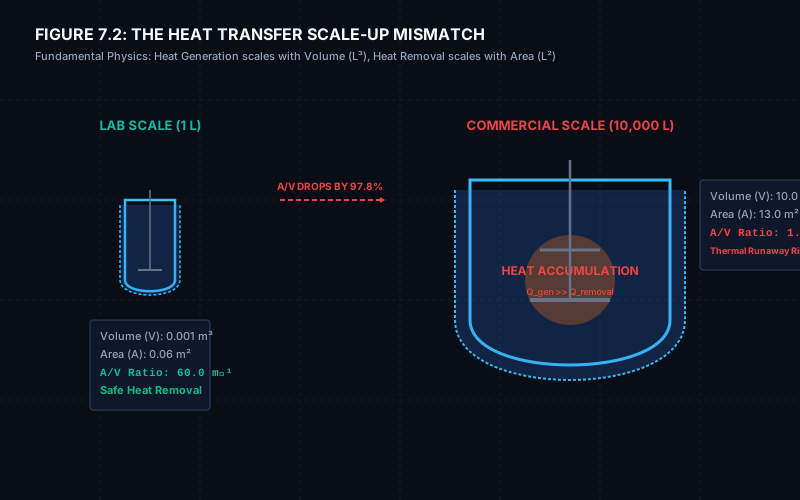
# 1. Mistake #1 — Scaling by Linear Volume Multiplication (The Geometric Area Collapse)
The most elementary scale-up failure is assuming that all geometric and physical dimensions scale proportionally with batch volume:
While total mass and mole quantities scale linearly (), geometric lengths, surface areas, and specific heat transfer ratios scale according to fractional non-linear power laws:
- Volume (): Scales with the cube of characteristic length:
- Characteristic Length (, Tank Diameter ): Scales with volume to the one-third power:
- Wetted Heat Transfer Surface Area (): Scales with length squared:
- Specific Surface Area Ratio (): Scales inversely with length:
# Quantitative Scaling Shift: 1 L Flask vs. 10,000 L Commercial Reactor
| Engineering Parameter | 1 L Laboratory Vessel | 100 L Pilot Reactor | 10,000 L Commercial Reactor | Scale Factor (1 L to 10 KL) | Governing Scaling Exponent |
|---|---|---|---|---|---|
| Working Liquid Volume () | (1 L) | (100 L) | (10,000 L) | ||
| Vessel Inside Diameter () | (100 mm) | (460 mm) | (2,150 mm) | ||
| Impeller Diameter () | (33 mm) | (153 mm) | (717 mm) | ||
| Wetted Heat Transfer Area () | |||||
| Specific Area Ratio () | Drops by () |
Because available jacket heat exchange area per unit volume drops from down to , an exothermic reaction releasing heat at a given rate per liter that causes a negligible jacket temperature difference in the lab will require an impossible cooling gradient in a 10 KL vessel.
# 2. Mistake #2 — Holding Agitator RPM Constant (The Power Explosion Trap)
A dangerous operational assumption is attempting to maintain the same rotational speed (RPM) across vessel scales ("The chemist ran it at 300 RPM in the lab, so run the 10 KL reactor at 300 RPM").
In agitated cylindrical vessels, power consumption () in the turbulent flow regime () is strictly governed by:
Where:
- = Agitator shaft power input (Watts, )
- = Dimensionless Impeller Power Number (drag coefficient: for hydrofoils, for pitched-blade turbines, for Rushton turbines)
- = Process fluid density ()
- = Rotational speed in revolutions per second ()
- = Impeller outer diameter (m)
Because power escalates with the 3rd power of speed () and the 5th power of impeller diameter (), holding speed constant () across a diameter scale ratio causes required motor power to explode:
Attempting to run a 10 KL agitator at 300–600 RPM would demand megawatts of power, instantly shearing the drive shaft and boiling the solvent.
# The Scale-Up Trade-Off:
If instead the engineer scales on Constant Power per Unit Volume ():
While volumetric energy dissipation () is held constant:
- Tip Speed increases by (), which can shatter shear-sensitive crystals.
- Blend time increases by (), increasing localized concentration gradients during reagent feeding!
# 3. Mistake #3 — Ignoring Characteristic Mixing Timescales & Damköhler Numbers
At the 1-liter bench scale, liquid turnover occurs in 1 to 2 seconds. In a 10,000 L commercial reactor, bulk circulation (macromixing) requires 30 to 90 seconds, turbulent inertial eddy breakup (mesomixing) requires 0.5 to 2 seconds, and molecular diffusion across viscous batchelor scales (micromixing) requires 10 to 50 milliseconds.
Timescale Comparison:
  tau_rxn  : Chemical Reaction Half-Life
  tau_micro: Micromixing Engulfment Time (Molecular Level)
  tau_meso : Feed Plume Turbulent Dispersion Time
  tau_macro: Bulk Vessel Circulation Time (Blend Time)

  IDEAL SCALE-UP REGIME:        tau_micro < tau_meso < tau_macro << tau_rxn  (Kinetic Control)
  DISASTROUS SCALE-UP REGIME:   tau_rxn << tau_micro < tau_meso < tau_macro  (Mixing Control)
# The Damköhler Number for Mixing ()
To predict whether a reaction will suffer selectivity loss upon scale-up, engineers evaluate the Damköhler Number for Mixing:
- Kinetic Regime (): Reaction half-life is long (). Reagents blend uniformly before significant chemical reaction occurs. The reaction proceeds homogeneously across the entire vessel; scale-up is seamless.
- Diffusion / Mixing-Controlled Regime (): Chemical reaction occurs faster than fluid blending (, typical of fast acylations, nitrations, brominations, and acid-base salt precipitations).
# The Competitive Reaction Failure Mechanism:
Consider a classical competitive-consecutive synthesis:
In a 10,000 L reactor under mixing control (), reagent dosed into the tank cannot disperse instantly. A localized, high-concentration plume forms near the feed point ().
Because is present in massive local excess, it attacks the freshly formed product before can diffuse away, producing unacceptable levels of Impurity that were completely undetected in the laboratory flask!
# 4. Mistake #4 — The Heat Removal Wall ( Shrinkage & Thermal Runaway)
In any exothermic chemical synthesis, the rate of heat generation () is strictly proportional to the total batch volume ():
Conversely, the rate of jacket heat removal () is strictly limited by the wetted surface area ():
Where:
- = Overall heat transfer coefficient ()
- = Wetted jacket surface area ()
- = Log-Mean Temperature Difference between process and jacket utility (K)
# The Thermal Mismatch:
- At 1 L, a reaction releasing represents a volumetric heat density of . With and :
A modest jacket cooling gradient easily removes all reaction heat.
- At 10,000 L, the identical volumetric heat density () releases () of heat. But has shrunk to :
A temperature gradient of is physically impossible when operating at (it would require chilling fluid at ). If the feed rate is not drastically throttled, the commercial batch temperature will escalate, triggering thermal runaway, solvent boiling, and dangerous pressure relief discharge.
# 5. Mistake #5 — Surface Dripping vs. Subsurface High-Shear Feed Dosing
In the laboratory, chemists add liquid reagents dropwise from an addition funnel through a neck on top of the flask. The drops hit the liquid surface right next to the stir bar.
In commercial manufacturing, piping reagents to a top dome nozzle and letting them free-fall onto the liquid surface creates severe yield and safety failures:
SURFACE DRIPPING (PLANT FAILURE):            SUBSURFACE DIP-PIPE (ENGINEERING SOLUTION):
     Top Nozzle Feed                              Top Nozzle Feed
          | (Droplet Free-Fall)                        | (Subsurface Pipe)
          v                                            |
   ~~~~~~~~~~~~ (Vapor Boiling & Fuming)               |
  [ Stagnant Baffle Shadow Plume ]                     |
  - Local Excess Reagent B                             v  Direct Discharge into
  - High Side-Product Impurities                 [Agitator High-Shear Impeller Stream]
  - Macromixing Time: 45 - 90 sec                - Engulfment Time: < 0.05 sec
                                                 - Uniform Stoichiometry
- Headspace Vapor Reaction: Volatile reagent vapors (e.g., thionyl chloride, triethylamine, pivaloyl chloride) react prematurely with solvent vapor in the reactor headspace, forming crusts on the vessel dome and nozzle necks.
- Thermal Boiling at Surface: Highly exothermic heats of dilution cause localized flash-boiling at the liquid surface, carrying unreacted active reagent into the condenser.
- Stagnant Zone Bypassing: Liquid dropped on the surface travels along the outer wall behind the baffles before reaching the impeller eye, prolonging micromixing engulfment time by a factor of 10.
# 6. Mistake #6 — Overlooking Gas-Liquid Mass Transfer (, Hatta Number & Flooding)
In multi-phase reactions (such as catalytic hydrogenations using Pd/C or Raney Nickel, oxidations, and carbonylations), reaction velocity is determined by the rate of gas dissolution into the liquid phase:
Where:
- = Volumetric gas-liquid mass transfer coefficient ()
- = Saturation equilibrium gas solubility at system temperature and partial pressure ()
- = Dissolved gas concentration in the bulk liquid phase ()
# The Hatta Number () Diagnostic:
To diagnose whether your reaction is limited by chemical kinetics or mass transfer:
- Slow Kinetic Regime (): Mass transfer is much faster than chemical consumption. The liquid is saturated with gas (). Scale-up depends strictly on temperature and catalyst loading.
- Fast Mass-Transfer Controlled Regime (): Gas molecules react instantaneously in the thin liquid boundary film surrounding gas bubbles. Bulk liquid concentration is starved ().
# The Plant Pitfall:
In the laboratory autoclave, intense vortexing at achieves . In a 5,000 L reactor equipped with a standard pitched blade turbine, frequently drops below .
Increasing catalyst concentration in the plant will NOT increase reaction rate—it only poisons the catalyst and produces de-halogenated or over-reduced impurities.
Solution: High-pressure hydrogenation reactors must utilize Hollow-Shaft Gas-Induction Impellers (e.g., Ekato GASJET or Biazzi Turbines) combined with high-flow concave dispersion turbines that continuously self-aspirate headspace gas and disperse it into micro-bubbles.
# 7. Mistake #7 — Assuming Constant Overall Heat Transfer Coefficient ()
Engineers frequently take a clean laboratory overall heat transfer coefficient () and apply it directly to size commercial jacketed reactors.
In industrial practice, is a composite series resistance:
# Typical Industrial Heat Transfer Coefficients across Reactor Types:
| Vessel Scale & Construction | Process Film () | Wall Material & Thickness () | Thermal Conductivity () | Effective Operating |
|---|---|---|---|---|
| 1 L Borosilicate Glass Flask | Borosilicate Glass | |||
| 5 KL SS316L Limpet Coil Reactor | Stainless Steel 316L | |||
| 5 KL Glass-Lined Steel (GLR) | Steel + Glass | (Glass) | ||
| 10 KL Hastelloy C-22 Reactor | Hastelloy C-22 |
Notice that in a Glass-Lined Reactor (GLR), the glass coating acts as an insulating thermal barrier with a low thermal conductivity (). The overall -value drops by over compared to stainless steel!
# 8. Mistake #8 — Ignoring Rheological Shifts & The Viscous "Cavern Effect"
Many API syntheses involve homogeneous starting solutions that precipitate dense slurries or polymerize into viscous masses during reaction, cooling, or antisolvent addition.
As fluid viscosity surges from (water-like) to (pseudoplastic slurry):
- Reynolds Number Plunge: The Impeller Reynolds number () drops from fully turbulent () down to laminar or deep transitional flow ().
- The Cavern Phenomenon: Fluid motion becomes strictly confined to an isolated, rotating liquid cylinder (a "cavern") immediately surrounding the impeller blade tips:
(where is the yield stress of the Bingham/pseudoplastic slurry)
3. Stagnant Annular Ring: Outside the cavern boundary, the fluid at the vessel walls and jacket interface becomes completely stationary.
4. Thermal Fouling: The process film coefficient () collapses by , leading to thermal runaway at the reactor core while solids bake onto the frozen jacket wall.
# 9. Mistake #9 — Misjudging Solid Suspension (), Crystal Attrition & Secondary Nucleation
In heterogeneous reactions and crystallizations, maintaining solids in complete suspension requires operating at or above the Zwietering Just-Suspended Speed ():
Where:
- = Dimensionless vessel geometry constant ()
- = Kinematic viscosity of liquid ()
- = Solid particle and liquid densities ()
- = Mean crystal diameter (m)
- = Solids mass concentration ratio (, )
- = Impeller diameter (m)
# The Crystallization Scale-Up Dilemma:
- Operating Below (): Dense crystals settle into the bottom dish and drain valve neck, forming stagnant cakes that halt reaction kinetics and block transfer lines.
- Operating Too Fast (): While is satisfied, the high peripheral tip speed shatters delicate crystal needles through mechanical collision against blades and baffles.
This shear-induced crystal attrition generates massive populations of sub-10 micron fines (secondary contact nucleation). The downstream consequence is disastrous: centrifuge filter cloths and Nutsche filter bags blind immediately, increasing cake wash times from 30 minutes to 18 hours!
# 10. Mistake #10 — Sub-Optimizing the Reactor While Blinding Downstream Operations
An industrial reactor does not exist in isolation. It is the central engine of an integrated manufacturing train:
Optimizing a reactor step without auditing downstream capacities causes severe plant bottlenecks:
- Condenser Overload: Boosting reactor heating rates to achieve a 1-hour solvent distillation creates vapor velocities exceeding , flooding the overhead shell-and-tube condenser and carrying active solvents into the vacuum pump.
- Specific Cake Resistance (): A filtration that takes 2 minutes on a laboratory Buchner funnel can take 24 hours on a Agitated Nutsche Filter Dryer (ANFD) if the reactor agitation conditions altered the Crystal Size Distribution (CSD).
- Cake Cracking & Solvent Trapping: Fine crystals form compressible filter cakes that crack under differential vacuum pressure, causing wash solvents to bypass the cake without washing out mother-liquor impurities.
# 11. Comprehensive Industrial Case Study: The $350,000 Failed Acylation in a 6,000 L Glass-Lined Reactor
To illustrate how these 10 physics-based transport phenomena intersect in real-world commercial manufacturing, consider the following documented API production failure and successful engineering remediation.
# A. The Chemistry & Laboratory Baseline (1 L Scale)
A pharmaceutical intermediate for an oncology API involves the rapid, highly exothermic acylation of a secondary amine intermediate () using pivaloyl chloride () in dichloromethane (DCM) with triethylamine () as an acid scavenger:
# Laboratory Conditions (1 L Glass Jacketed Flask):
- Batch charge: DCM containing Amine .
- Dosing: Neat pivaloyl chloride () added dropwise over 15 minutes via addition funnel.
- Agitation: 4-blade PTFE pitch turbine running at ().
- Batch temperature maintained tightly between and with a circulator bath.
- Laboratory Analytical Results: Conversion , Impurity , pure white crystalline needles, filtration time on Buchner funnel: 2.5 minutes.
# B. The Commercial Plant Disaster (6,000 L Scale)
The synthesis was scaled directly by a factor of into a standard commercial 6,000 L () Glass-Lined Reactor (GLR).
PLANT INPUT SPECIFICATIONS (R-201):
  Working Liquid Volume: 3,600 L
  Vessel Internal Diameter: T = 1,800 mm
  Agitator: 3-Blade Glass-Coated Retreat Curve Impeller (RCI), D = 600 mm (D/T = 0.33)
  Operating Speed: 80 RPM (VFD Maximum Torque Limit)
  Baffling: Single Glass-Lined Beaver-Tail Baffle with internal RTD thermowell
  Cooling Utility: -15°C Chilled Ethylene Glycol / Water via Jacket
# What Actually Happened in the Plant:
- The Heat Transfer Wall: Due to the glass lining and low jacket velocity, the overall heat transfer coefficient was only . Total wetted jacket area was .
To avoid exceeding the batch decomposition ceiling, plant operators were forced to throttle the pivaloyl chloride dosing pump from the planned 30 minutes to 4.5 hours! - The Surface Dosing Defect: Pivaloyl chloride was pumped through a 2-inch top nozzle on the vessel dome, free-falling onto the swirling liquid surface in the stagnant shadow of the single beaver-tail baffle.
- The Micromixing Breakdown: At , the bulk circulation time was , while the local turbulent dissipation rate at the surface was negligible ().
Local Damköhler number:
- Catastrophic Outcome:
- Incoming pivaloyl chloride formed a massive concentrated unmixed plume at the liquid surface.
- Reagent attacked the already formed product , generating excessive amounts of Di-Acylated Impurity .
- HPLC analysis revealed Impurity spiked to (specification limit was ).
- The high impurity profile altered the subsequent cooling crystallization: the product precipitated as an amorphous gooey gum that completely blinded the Agitated Nutsche Filter Dryer (ANFD). Filtration stalled after 28 hours.
- Financial Loss: The entire batch was contaminated and had to be incinerated. Total batch loss: $350,000 USD and 3 weeks of plant downtime.
# C. Engineering Root-Cause & 4-Step Remediation Strategy
A cross-functional team of reaction engineering and scale-up specialists conducted an emergency transport phenomena audit and implemented four decisive hardware and operational modifications:
+=======================================================================================+
|                   4-STEP SCALE-UP REMEDIATION BLUEPRINT (R-201)                      |
+=======================================================================================+
|                                                                                       |
|   1. SUBSURFACE DIP PIPE INJECTION:                                                   |
|      Installed an SS316L/PTFE dip pipe discharging reagent neat B directly into the   |
|      high-shear discharge tip of the lower impeller (tau_micro reduced from 4s to 35ms)|
|                                                                                       |
|   2. FEED REAGENT DILUTION (30% in DCM):                                              |
|      Diluted pivaloyl chloride with DCM solvent prior to dosing, dropping local       |
|      stoichiometric excess at the injection point by 70%.                             |
|                                                                                       |
|   3. EXTERNAL HIGH-VELOCITY PUMP-AROUND HEAT EXCHANGER (SIDE-ARM):                   |
|      Installed a canned-motor pump circulation loop (40 m³/h) through a compact       |
|      Hastelloy C-22 plate heat exchanger (U = 850 W/m²·K, Area = 18 m²).              |
|      Bypassed GLR glass jacket bottleneck; increased cooling capacity to 350 kW!       |
|      Allowed dosing duration to be cut from 4.5 hours down to 45 minutes!             |
|                                                                                       |
|   4. CLOSED-LOOP INLINE PAT CONTROL (METTLER TOLEDO ReactIR):                         |
|      Installed an inline mid-IR diamond probe to monitor conversion of amine A and    |
|      modulate the dosing pump automatically to maintain zero unreacted B accumulation.|
+=======================================================================================+
# D. The Validation Batch Results
With these four engineering controls in place, Repeat Batch #2 was executed at full commercial scale ():
| Process Metric | Laboratory Baseline (1 L) | Failed Initial Commercial Batch (6 KL) | Remediated Engineering Batch (6 KL) |
|---|---|---|---|
| Reagent Addition Time | 15 minutes | 270 minutes (4.5 hours) | 45 minutes |
| Heat Removal Mechanism | Lab circulator bath | Vessel jacket only () | External Plate HEX () |
| Feed Dosing Location | Surface dropwise | Surface free-fall | Subsurface Impeller Tip Jet |
| Damköhler Number () | (Kinetic Control) | (Severe Mass Transfer Control) | (Near Kinetic Control) |
| Peak Batch Temperature | (Exotherm spike) | (Controlled) | |
| Impurity D (Bis-Adduct) | (BATCH REJECTED) | (PASS, Spec ) | |
| Isolated Final Yield | (Scrapped to waste) | ||
| ANFD Filtration Duration | 2.5 minutes | > 28 hours (Blinded filter) | 42 minutes (Clean crystal bed) |
By substituting emotional guesswork with quantitative transport phenomena calculations, the plant transformed an un-manufacturable chemistry into a stable, highly profitable commercial manufacturing process.
# 12. Master Scale-Up Parameter Decision Matrix
When scaling an agitated chemical reactor, no single operating condition can satisfy all physical similitudes simultaneously. Engineers must identify the primary rate-limiting transport phenomenon and select the corresponding governing scale-up rule:
| Limiting Process Phenomenon | Primary Governing Scale-Up Rule | Rotational Speed Scaling Equation | Scale Exponent () | Key Hazard of Inappropriate Scaling |
|---|---|---|---|---|
| Fast Competitive Synthesis / Feed Plumes | Constant Mixing Time () | Power explodes by ; impossible in large reactors. | ||
| Gas-Liquid / Liquid-Liquid Mass Transfer | Constant Power per Unit Volume () | Tip speed increases; fragile crystals undergo attrition. | ||
| Shear-Sensitive Crystallization & Biologics | Constant Impeller Tip Speed () | Mixing time increases; localized concentration gradients form. | ||
| Heterogeneous Catalyst Suspension | Zwietering Just-Suspended Speed () | Solids settle below ; catalyst starved of reactants. | ||
| Exothermic Temperature-Limited Reactions | Constant Heat Flux per Unit Area () | Dosing throttled to match | Heat Transfer Limited | Thermal runaway, byproduct accumulation, cycle delays. |
# 13. The 5-Stage Protocol for Bulletproof API Technology Transfer
To eliminate scale-up surprises before entering commercial production, leading pharmaceutical engineering organizations execute this 5-stage scale-up de-risking protocol:
[Stage 1: Reaction Calorimetry & Kinetics] (Mettler RC1e, ARC, ReactIR)
  - Measure delta-H_rxn, adiabatic temperature rise (delta-T_ad), and TMR_ad.
  - Determine true chemical reaction order and activation energy (Ea).
                         |
                         v
[Stage 2: Hydrodynamic & Scale-Down Modeling] (Visimix, DynoChem, CFD)
  - Simulate blend times, micro-mixing engulfment times, and shear rates.
  - Execute scale-down experiments in lab reactors mimicking plant blend times.
                         |
                         v
[Stage 3: Intermediate Pilot Demonstration] (50 L to 500 L Scale)
  - Validate impurity profiles under realistic plant dosing durations.
  - Optimize crystal seed loading, supersaturation profiles, and CSD.
                         |
                         v
[Stage 4: Downstream Unit Operation Capacity Audit]
  - Calculate ANFD cake permeability and specific cake resistance (alpha_c).
  - Verify overhead condenser vapor velocity and vacuum pump volumetric sweep.
                         |
                         v
[Stage 5: Commercial Plant Commissioning & PAT Integration]
  - Install subsurface dip pipes and verify VFD torque and critical speed envelopes.
  - Deploy inline PAT probes (FBRM, ReactIR) for real-time closed-loop dosing control.
# 14. Interactive Engineering Calculators & Sizing Tools
Need to calculate power requirements, tip speeds, Reynolds numbers, and scale-up parameters for your batch reactor? Access our interactive chemical engineering suite:
- Batch Reactor Scale-Up & Agitator Sizer →
Translate lab parameters to plant scale using constant , tip speed, or blend time. Compute motor kilowatts, operating torque, and Reynolds numbers. - Reactor Shaft Mechanical Sizing Calculator →
Verify ASME shaft diameters, dynamic bending moments, API 682 seal runout limits (), and critical whirling speeds. - Heat Exchanger Design & LMTD Calculator →
Size external pump-around heat exchangers, determine log-mean temperature differences, and calculate required surface areas. - Tank & Reactor Inertization Sizing Calculator →
Calculate nitrogen purge volumes, vacuum-pressure swing cycles, and Limiting Oxygen Concentration (LOC) compliance per NFPA 69.
# Applicable Engineering Standards & Industry Codes
The engineering methodologies, design correlations, and safety criteria detailed in this article adhere to the following international standards and industry codes:
- US FDA 21 CFR Part 211.65 & 211.67: Equipment Design, Size, and Cleaning Maintenance in Pharmaceutical Manufacturing.
- EU GMP Annex 1: Manufacture of Sterile Medicinal Products.
- ISPE Baseline Pharmaceutical Engineering Guide (Volume 1 to 7): Bulk Active Pharmaceutical Ingredients, Water & Steam Systems, and Commissioning & Qualification.
- DIN 28131 & DIN 28161: Agitated Vessels and Agitator Shaft Mechanical Design Standards.
- ASME B106.1M: Design of Transmission Shafting for Agitated Equipment.
- API 682 / ISO 21049: Shaft Sealing Systems for Centrifugal and Agitated Rotary Equipment.
- ASME Boiler and Pressure Vessel Code (BPVC) Section VIII, Division 1 & 2: Rules for Construction of Pressure Vessels and Jacketed Chemical Reactors.
- WHO Technical Report Series No. 961: Good Manufacturing Practices for Pharmaceutical Products.