# Givaudan (2024) & T2 Laboratories (2007) Runaway Reaction Autopsy: CSB Investigations & API Process Safety Lessons
Thermal runaway reactions represent the single most destructive hazard class in batch chemical processing and pharmaceutical API manufacturing. When reaction heat generation () outpaces jacket heat removal (), exponential temperature surge triggers secondary decomposition reactions, violent non-condensable gas evolution, and catastrophic pressure vessel rupture.
This technical autopsy compares two landmark industrial runaway explosions investigated by the U.S. Chemical Safety and Hazard Investigation Board (CSB):
- The T2 Laboratories Explosion (Jacksonville, Florida, December 2007)
- The Givaudan Sense Colour Explosion (Louisville, Kentucky, November 2024 — CSB Final Investigation Report)
Despite occurring 17 years apart in different chemical sectors, both disasters share an identical, systemic failure pattern that provides crucial engineering lessons for API plant managers, process chemists, and safety instrumented system () designers.
# 1. Forensic Case Study 1: T2 Laboratories Explosion (Jacksonville, FL, 2007)
# 1.1 Process Chemistry & Reactor Operating Setup
T2 Laboratories manufactured methylcyclopentadienyl manganese tricarbonyl (), a gasoline anti-knock additive. The initial step reacted sodium metal with methylcyclopentadiene () in diglyme solvent:
+----------------------------------------------------------------------------+
|                  T2 LABORATORIES EVENT TREE AUTOPSY                        |
|                                                                            |
| 1. Coolant Water Line Blocked ---> 2. Jacket Heat Removal (Qrem) Drops to 0|
|                                                |                           |
| 4. Catastrophic Detonation <--- 3. Secondary Exothermic Runaway @ 190°C    |
|    (TNT Equiv: 1.4 Tons)         Diglyme & MCP Gas Rate > 190 bar/min      |
+----------------------------------------------------------------------------+
# 1.2 Forensic Root Cause Findings (CSB Report)
- Zero Calorimetric Hazard Screening: No Differential Scanning Calorimetry (DSC), Accelerating Rate Calorimetry (ARC), or Reaction Calorimetry (RC1) had ever been performed. T2 engineers had no quantitative data for , , or MTSR.
- The Scale-Up Penalty: The process was scaled up 7-fold from a pilot rig to a () reactor. Heat transfer area per unit volume () dropped by :
- Single-Point Cooling Water Failure: A blockage in the jacket cooling water line eliminated heat removal. As batch temperature reached , a violent secondary decomposition of the organometallic mixture initiated.
- Relief Valve Undersizing: The installed 3-inch relief valve was sized for simple solvent vapor venting—not for two-phase flashing reactive gas evolution. Pressure surged to , violently tearing the reactor shell apart ( TNT equivalent), killing 4 workers, injuring 32 others, and demolishing the plant.
# 2. Forensic Case Study 2: Givaudan Sense Colour Explosion (Louisville, KY, 2024)
# 2.1 Process Setup & Caramel Reaction Physics
On 12 November 2024, a () stainless steel batch reactor ("Reactor 6") exploded at the Givaudan Sense Colour plant in Louisville, Kentucky during caramel manufacturing. The CSB issued its final investigation report.
# 2.2 Forensic Root Cause Findings (CSB Final Report)
- The "Food-Grade Raw Material" Hazard Trap: Plant personnel assumed sugar syrup was thermally benign. Post-incident APTAC testing revealed that invert sugar undergoes rapid exothermic decomposition with massive gas release at temperatures within the normal operating window ().
- Vent Valve Stuck Closed: The automated reactor vent valve, which normally opened to release water vapor and limit pressure to , failed mechanically in the closed position.
- Loss of Evaporative Cooling: Closing the vent path eliminated evaporative cooling. Steam heating continued, driving self-heating past the critical decomposition threshold.
- Relief System Failure: The reactor was equipped with a rupture disc set at . The rupture disc functioned mechanically, but was 4 times smaller than required for the actual sugar decomposition gas generation rate. Pressure reached (), killing 2 employees, injuring 3, and causing \40\text{M}+$ in offsite structural damage.
# 3. Side-by-Side Comparative Autopsy Matrix
| Engineering Metric | T2 Laboratories Explosion (2007) | Givaudan Sense Colour Explosion (2024) | API Process Engineering Takeaway |
|---|---|---|---|
| Primary Process Class | Organometallic synthesis (MCMT) | Carbohydrate caramelization | High; API processing utilizes both organometallics and active sugar excipients |
| Primary Failure Trigger | Cooling water jacket valve blockage | Automated vent valve stuck closed | Single valve failure must NOT cause uncontrolled thermal runaway |
| Calorimetry Data | Zero calorimetry tests performed | 2012 internal test flagged exotherm, but was never acted upon | Calorimetry results MUST be generalized across all plant recipes and SOPs |
| Relief Sizing Method | Single-phase vapor pressure sizing | Undocumented legacy sizing ( undersized) | Relief devices MUST be sized via DIERS two-phase flashing flow methodology |
| Human Factors | Operators saw rising but lacked runaway training | Control room attempted troubleshooting for 18 min instead of evacuating | Clear Safe Operating Limits (SOL) paired with automatic evacuation triggers |
| Consequences | 4 fatalities, 32 injuries, plant destroyed | 2 fatalities, 3 injuries, \40\text{M}+$ damage, site demolished | Catastrophic loss of life and complete facility destruction |
# 4. Stoessel Criticality Class Assessment & DIERS Sizing Math
# 4.1 Stoessel Thermal Risk Matrix
To quantify thermal runaway risk, process safety engineers calculate the Maximum Temperature of the Synthesis Reaction (MTSR) relative to the solvent boiling point () and the temperature for Time to Maximum Rate of 24 hours ():
Stoessel Criticality Classes:
- Class 1: MTSR < Tb < Td24 --------> Low Hazard (Boiling removes heat)
- Class 2: MTSR < Td24 < Tb --------> Low Hazard (No decomposition trigger)
- Class 3: Td24 < MTSR < Tb --------> High Hazard (Decomposition triggered before boiling)
- Class 4: Td24 < Tb < MTSR --------> Extreme Hazard (Boiling occurs during runaway)
- Class 5: Tb < Td24 < MTSR --------> CATASTROPHIC HAZARD (T2 & Givaudan Category!)
# 4.2 DIERS Homogeneous Equilibrium Model (HEM) Relief Sizing
For reactive systems generating non-condensable gas and two-phase flashing flow, the required emergency vent area is calculated via DIERS methodology:
Where:
- = Vessel total volume ()
- = Two-phase mixture density ()
- = Choked two-phase mass flux ()
- = Self-heating rate at relief set pressure ()
# 5. The 6 Non-Negotiable Rules for API Process Safety
- Mandatory Calorimetry Gate: No synthesis step may be scaled up beyond bench scale () without DSC screening and reaction calorimetry (RC1/ARC) establishing , , MTSR, and Stoessel Class.
- Re-Evaluate Scale-Up Gates: Re-verify thermal hazard parameters at , , and full commercial scale to account for surface-to-volume () cooling degradation.
- DIERS Two-Phase Relief Sizing: Relief valves and rupture discs must be sized for worst-case non-condensable gas and two-phase flashing flow, not simple solvent vapor pressure.
- Independent Safety Instrumented Systems (SIS): Install SIL-rated high-temperature/high-pressure automated trips independent of the basic process control system (BPCS).
- Generalize Hazard Findings: If reactivity testing identifies a hazard in one product or recipe, screen all related products, excipients, and raw materials across the site portfolio.
- Enforce Hard Safe Operating Limits (SOL): Define clear and limits. If exceeded, operators must evacuate immediately rather than attempting control-room troubleshooting.
# 6. Applicable Engineering Standards & Codes
- DIERS Project Manual: Design Institute for Emergency Relief Systems (AIChE).
- OSHA 29 CFR 1910.119: Process Safety Management of Highly Hazardous Chemicals.
- IEC 61511: Functional safety - Safety instrumented systems for the process industry sector.
- NFPA 68: Standard on Explosion Protection by Deflagration Venting.
# Historical Background & Foundation
# Runaway Reaction Risks and Technology Transfer in Multipurpose Process Equipment: Thermal Hazards, Advanced Instrumentation, and Safety Control Logics
In contract development and manufacturing organizations (CDMOs) and multi-product pharmaceutical synthesis facilities, multipurpose batch reactors are tasked with executing dozens of distinct chemical transformations within the same processing envelope.
While multi-product utilization maximizes equipment ROI, handling energetic reaction chemistries across different vessel geometries, heat transfer jackets, and metallurgy introduces severe thermal runaway hazards.
Transferring an exothermic synthetic process from a 1 L laboratory flask or 20 L pilot unit into a commercial 5,000 L () glass-lined or Hastelloy reactor is not simply a matter of multiplying raw material charges. Without an integrated, multilayered instrumentation, process control, and safety automation framework, an unpredicted cooling deficit or unreacted reagent accumulation will trigger an exponential thermal runaway in minutes—resulting in ruptured rupture disks, mechanical seal blowouts, toxic vapor releases, or catastrophic vessel explosions.
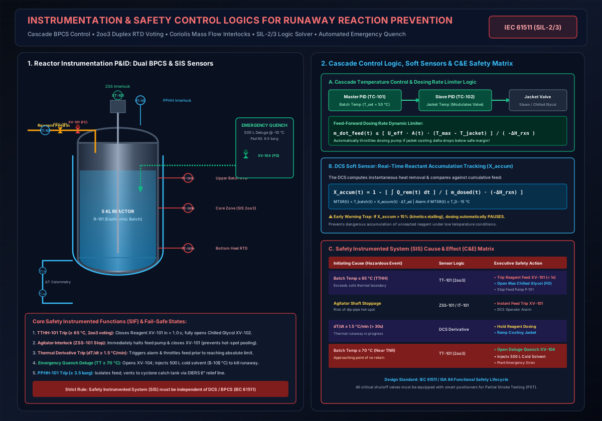
This comprehensive chemical engineering guide details the physics of runaway reactions, calorimetric hazard screening, and the specific field instrumentation, cascade control loops, soft-sensor algorithms, and Safety Instrumented System (SIS / SIL-2/3) interlock logics required to safely execute technology transfer in multipurpose manufacturing plants.
# 1. The Physics of Thermal Runaways & The Dynamic Energy Balance
A thermal runaway is an autocatalytic feedback loop governed by the competition between chemical heat generation () and equipment heat removal capacity ().
# A. Exponential Arrhenius Heat Generation ()
The heat release rate () from an exothermic reaction follows an exponential Arrhenius temperature dependence:
Where:
- = Specific reaction enthalpy (exotherm) ( or )
- = Liquid reaction volume ()
- = Arrhenius pre-exponential frequency factor ( or )
- = Reaction activation energy ()
- = Universal gas constant ()
- = Absolute batch temperature ()
- = Molar concentrations of reactants ()
# B. Linear Jacket Heat Removal ()
The heat removal rate () through the reactor jacket or internal cooling coil follows Newton's Law of Cooling with a linear temperature dependence:
Where:
- = Overall heat transfer coefficient ()
- = Wetted heat transfer surface area ()
- = Cooling utility temperature in the jacket ()
Heat Rate (q) [kW]
^
|                                          / q_gen (Arrhenius Exponential)
|                                        /
|                                      /
|                                    /
|                    q_rem (Linear) / . . . . Uncontrolled Runaway Zone (q_gen > q_rem)
|                        /        /
|                      /        /
|                    /   o    /  <- Critical Tangent Point: Temperature of No Return (TNR)
|                  /   /
|                /  /  <- Stable Operating Point (q_gen = q_rem)
|              //
|            //
+------------------------------------------------------------>
                                                        Temperature (T) [°C]
# C. The Temperature of No Return () & Critical Ignition
The Temperature of No Return () is the dynamic critical temperature threshold where the rate of heat generation curve becomes tangent to the heat removal line:
- If : The cooling jacket has sufficient thermal driving force to bring an elevated batch temperature back down to the target setpoint.
- If : Heat generation permanently outpaces maximum cooling capability (). The batch temperature self-accelerates exponentially toward secondary decomposition.
# 2. The Scale-Up Heat Transfer Deficit: Lab vs. Commercial Scale
The most dangerous pitfall during technology transfer is assuming that because a reaction ran smoothly in a 1 L laboratory flask or 20 L pilot vessel, it will be equally controllable in a 5,000 L plant reactor.
# Geometric Scaling Law for Surface-Area-to-Volume Ratio:
For geometrically similar cylindrical vessels with aspect ratio :
| Scale Parameter | Laboratory Flask (1 L) | Pilot Reactor (20 L) | Commercial GLR (5,000 L) | Commercial SS Reactor (10,000 L) |
|---|---|---|---|---|
| Vessel Internal Diameter () | ||||
| Working Liquid Volume () | ||||
| Wetted Heat Transfer Area () | ||||
| Area-to-Volume Ratio () | ||||
| Relative Heat Dissipation Deficit | (Baseline) |
# Material of Construction (MOC) Heat Transfer Variations:
In multipurpose plants, swapping between glass-lined steel (GLR) and metallic alloys introduces massive variations in overall heat transfer coefficient ():
- Glass-Lined Steel Reactors (GLR): (The glass barrier with low thermal conductivity forms a severe thermal resistance).
- Hastelloy C-22 / C-276 Vessels: .
- Stainless Steel (SS316L) Vessels: .
# 3. 10 Critical Failure Scenarios in Multipurpose Manufacturing
A comprehensive Process Hazards Analysis (PHA / HAZOP) must analyze the following 10 reactive chemical failure modes:
- Reactant Accumulation Trap: Low batch temperature stalls kinetics during semi-batch dosing (). A subsequent temperature rise ignites the entire unreacted inventory simultaneously.
- Agitation Loss & Localized Dip-Pipe Hot-Spots: Reagent pools at the feed pipe discharge without dispersing. Localized temperature exceeds decomposition onset (), triggering bulk runaway.
- Liquid-Liquid Phase Stratification: Immiscible aqueous-organic phases separate on mixing failure. Re-starting agitation mixes the stratified reactants instantaneously, releasing gigajoules of energy.
- Cross-Contamination & Residual CIP Heel Catalysis: Trace acidic or basic cleaning heels (, ) in bottom valves act as unplanned homogeneous catalysts, dropping decomposition onset by .
- Autocatalysis & Extended Cycle Holds: Autocatalytic intermediates held at elevated temperature during plant delays consume their induction time (), causing spontaneous ignition.
- Chemical Rollover in Storage Receivers: Density inversion of stratified liquid layers causes violent spontaneous mixing and massive gas release.
- Inhibitor Depletion in Vapors: Free-radical inhibitors (MEHQ, BHT) remain in the liquid pot during monomer distillation; pure vapor condensing in overhead lines auto-polymerizes and detonates.
- Preferential Solvent Stripping: Solvent boiling off under vacuum increases reagent concentration (), eliminating the thermal heat sink.
- Overcooling Stalls: Freezing or precipitating the batch during dosing leads to silent reagent accumulation followed by catastrophic thermal surge on reheating.
- Trace Metal Catalysis (MOC Drift): Chemistry validated in glass-lined equipment undergoes Lewis acid-catalyzed decomposition when placed in stainless steel ( ions).
# 4. Reaction Calorimetry Suite & Stoessel Criticality Matrix
Technology transfer without quantitative calorimetry is unacceptable. A complete thermal testing protocol requires three instruments:
- DSC (Differential Scanning Calorimetry): Rapid screening of decomposition enthalpy () and onset temperature ().
- RC1e / Reaction Calorimetry: Isothermal measurement of true reaction enthalpy (), reagent accumulation curve , adiabatic temperature rise , and Maximum Temperature of Synthesis Reaction ().
- ARC (Accelerating Rate Calorimetry) / VSP2: True adiabatic runaway testing measuring decomposition onset (), peak self-heating rate , pressure rate , and Time-to-Maximum-Rate ().
# The Stoessel 5-Class Criticality Framework:
| Criticality Class | Temperature Hierarchy | Physical Consequence of Total Cooling Failure | Mandatory Instrumentation & Control Requirements |
|---|---|---|---|
| Class 1 | Safe. Reaction exotherm cannot reach boiling or decomposition. | Standard basic process control (BPCS). | |
| Class 2 | Moderate risk. Exotherm remains below boiling and decomposition. | Dual temperature alarms; automatic dosing shutoff on high temp. | |
| Class 3 | Tempered system. Solvent boiling removes heat, capping temperature below . | High-capacity overhead condenser; DIERS vapor relief sizing. | |
| Class 4 | HIGH HAZARD: Synthesis exotherm triggers secondary decomposition before solvent can boil! | Fast-acting automated emergency quench pot; SIL-2 SIF interlocks. | |
| Class 5 | EXTREME HAZARD: Solvent boils, but decomposition triggers anyway, leading to explosive overpressure. | Redundant DIERS two-phase ERS; dual rupture disks; kill pot deluge. |
# 5. Reactor Field Instrumentation Architecture (The Sensor Layer)
An exothermic batch reactor must be equipped with dedicated, physically segregated sensors for both the Basic Process Control System (BPCS) and the Safety Instrumented System (SIS) per IEC 61511 / ISA 84 standards:
+----------------------------------------------------------------------------------------------------+
|                         REACTOR FIELD INSTRUMENTATION ARCHITECTURE                                 |
+------------------------------------+----------------------------------+----------------------------+
| 1. TEMPERATURE (Primary Defense)   | 2. PRESSURE & LEVEL SENSING      | 3. DOSING & AGITATION      |
+------------------------------------+----------------------------------+----------------------------+
| * Multi-Elevation Duplex Pt-100    | * Dual Tantalum Diaphragm PTs    | * Coriolis Mass Flowmeter  |
|   RTDs (Bottom, Middle, Upper).    |   (BPCS PT-101A, SIS PT-101B).   |   (FT-101, kg/h true mass).|
| * 2oo3 Voting for SIL-2 Trip.      | * Non-Contact Radar Level (LT).  | * Double Block & Bleed     |
| * Jacket In/Out Delta-T RTDs       | * Differential Pressure (d/p)    |   Fail-Closed Valves (XV). |
|   (Calorimetric Heat Tracking).    |   Level Swell & Foam Detector.   | * Digital Agitator Speed   |
| * Fast Response Thin-Wall Sleeves. | * Overpressure Interlocks.       |   & Zero-Speed Switch (ZSS)|
+------------------------------------+----------------------------------+----------------------------+
# A. Temperature Measurement Architecture:
- Multi-Elevation Duplex Pt-100 RTDs (Class A):
- Bottom Dish RTD (): Submerged during initial solvent heel charging (active from volume).
- Mid-Level Core Zone RTD (): Primary sensing point during active dosing ( volume).
- Upper Batch RTD (): Monitors top batch layer ( volume).
- 2oo3 Voting Logic for SIS Trip:
- Triplicate RTD elements evaluated by the safety logic solver. If any 2 out of 3 transmitters detect , the safety interlock executes immediately. This eliminates spurious trips while guaranteeing zero single-point sensor failure.
- Thermowell Optimization:
- To achieve a thermal time constant , thermowells must use thin-wall Hastelloy C-22 or Tantalum sleeves packed with thermally conductive silver paste, with wake vibration frequencies certified to ASME PTC 19.3 TW.
- Jacket Differential Temperature Transmitters:
- High-precision RTDs on the jacket utility inlet () and outlet () continuously calculate real-time jacket thermal flux:
# B. Reagent Dosing & Flow Control:
- Coriolis Mass Flowmeters ():
- Volumetric flowmeters fail during technology transfer due to solvent thermal expansion. Coriolis mass flowmeters measure true mass flow () with accuracy regardless of temperature, density, or viscosity changes.
- Double Block and Bleed (DBB) Fail-Closed (FC) Valves:
- The dosing line features two automated pneumatic valves in series: an air-to-open regulating control valve () modulated by BPCS, followed by an independent safety emergency isolation valve () operated by the SIS logic solver. Both valves are Fail-Closed (FC / Spring-Return), snapping shut in upon loss of instrument air or electrical power.
# C. Agitator Operational Verification:
- Digital Speed Sensor () & Zero-Speed Switch ():
- Proximity sensors on the agitator shaft verify actual physical rotation (not merely motor contactor status).
- Motor Power / Current Transducer ():
- Measures active motor power draw. If liquid viscosity drops or blade decoupling occurs, low motor load trips an alarm.
# 6. Advanced Process Control (BPCS) Logics & Soft Sensors
Modern DCS platforms (Emerson DeltaV, Honeywell Experion, ABB 800xA, Yokogawa Centum) must implement the following advanced control strategies:
[ Master Batch Temp Controller (TC-101) ]
                  | (Cascade Setpoint)
                  v
[ Slave Jacket Temp Controller (TC-102) ] ---> [ Modulates Heating / Cooling Valves ]
                  ^
                  | (Dynamic Clamping Limit)
[ Feed-Forward Dosing Rate Limiter (FIC-101) ] ---> [ Throttles Reagent Mass Flow (FT-101) ]
# A. Cascade Temperature Control:
- Master Controller (): Measures the internal batch temperature () and outputs a dynamic temperature setpoint () to the slave loop.
- Slave Controller (): Measures jacket temperature () and modulates the 3-way thermal control valves (steam, cooling water, chilled glycol) to maintain the jacket setpoint.
- Benefit: Eliminates the thermal lag of the vessel wall and provides rapid response to external utility pressure fluctuations.
# B. Dynamic Feed-Forward Dosing Rate Limiter:
The dosing flow controller () is continuously clamped by a feed-forward algorithm calculating the maximum permissible chemical heat release:
- If jacket cooling approaches maximum capacity (), the DCS automatically throttles the reagent dosing rate.
- If batch temperature rises above setpoint by more than , dosing flow is ramped down proportionally, and automatically paused if .
# C. Real-Time Reactant Accumulation Soft-Sensor ( Tracker):
The DCS executes an online continuous energy balance, comparing cumulative heat removed against total reagent fed:
From , the DCS computes instantaneous :
The Accumulation Safety Interlock: If the soft sensor detects (indicating that kinetics have stalled due to low temperature or catalyst deactivation), the DCS generates a high-priority alarm and automatically pauses reagent dosing. Dosing cannot resume until the exotherm catches up and accumulation drops below .
# D. Thermal Derivative Early Warning ( Trigger):
- An absolute temperature alarm at may occur too late if the batch is accelerating at .
- The DCS continuously calculates the derivative .
- If sustained for , the DCS immediately ramps cooling to and halts reagent feeding before the batch reaches dangerous temperature levels.
# 7. Safety Instrumented Systems (SIS / SIL-2/3) & Cause & Effect (C&E) Matrix
Per IEC 61511 standards, safety interlocks must execute in an independent, certified Safety Logic Solver (e.g. Triconex / DeltaV SIS) completely segregated from the BPCS network.
+----------------------------------------------------------------------------------------------------+
|                         SAFETY INSTRUMENTED SYSTEM CAUSE & EFFECT MATRIX                           |
+------------------------------+--------------------+------------------------------------------------+
| Initiating Cause (Hazard)    | Sensor Architecture| Executive Safety Actions (Outputs)             |
+------------------------------+--------------------+------------------------------------------------+
| 1. High-High Temperature     | TT-101 (2oo3       | • De-energize XV-101 (Reagent Feed Cutoff <1s).|
|    (TTHH >= 65 °C)           | voting logic)      | • Fully open XV-102 (Max Chilled Glycol FO).   |
|                              |                    | • Stop Reagent Feed Pump (P-101 Trip).         |
+------------------------------+--------------------+------------------------------------------------+
| 2. Agitator Shaft Stoppage   | ZSS-101 / IT-101   | • Immediate trip of Reagent Feed Valve XV-101. |
|    (Loss of Mixing)          | (Speed + Current)  | • Prevents localized dip-pipe hot-spot pooling.|
+------------------------------+--------------------+------------------------------------------------+
| 3. High-High Pressure        | PT-101B (SIL-2     | • Immediate trip of Reagent Feed Valve XV-101. |
|    (PPHH >= 3.5 barg)        | Diaphragm Seal)    | • Opens Emergency Vent to Scrubber XV-103.     |
+------------------------------+--------------------+------------------------------------------------+
| 4. Critical Thermal Runaway  | TT-101 (2oo3       | • Opens Emergency Quench Deluge Valve XV-104.  |
|    (T_batch >= 70 °C ~ TNR)  | voting logic)      | • Injects 500 L cold solvent (-10 °C) in <10s. |
|                              |                    | • Plant Emergency Evacuation Siren.            |
+------------------------------+--------------------+------------------------------------------------+
| 5. Utility Air / Power Loss  | Hardwired Spring-  | • All Feed Valves fail CLOSED (FC).            |
|    (Blackout Condition)      | Return Actuators   | • Emergency Glycol Jacket fails OPEN (FO).     |
+------------------------------+--------------------+------------------------------------------------+
# 8. Emergency Mitigation & Active Kill Systems
When a thermal runaway crosses the Temperature of No Return (), passive cooling is mathematically impossible. Multipurpose plants handling Stoessel Class 4 and 5 reactions must deploy active emergency mitigation systems:
                  +-------------------------------------------------------------+
                  |         PRESSURIZED AUTOMATED EMERGENCY QUENCH POT          |
                  +-------------------------------------------------------------+
                  |  - Nitrogen Pad: 6.0 barg constant overpressure             |
                  |  - Fluid Charge: 500 L Cold Solvent (-10 °C) / Radical Kill |
                  |  - Actuation: Dual SIL-2 Fail-Open Valves (XV-104A/B)       |
                  |  - Injection Time: < 10 seconds through dual spray rings    |
                  +-------------------------------------------------------------+
                                                |
                                                v
                                    +-----------------------+
                                    |  5 KL BATCH REACTOR   |
                                    |  (Batch Temp Drops    |
                                    |   from 70 °C -> 48 °C)|
                                    +-----------------------+
# A. Pressurized Automated Solvent Quench Deluge Pot:
- A dedicated pressure vessel mounted above the reactor, pre-charged with of cold reaction solvent (toluene at ) under nitrogen pressure.
- Actuated by dual fail-open pneumatic valves () wired to the SIS.
- Thermal Quench Mechanism: Injects in directly into the liquid core via internal distribution nozzles, diluting reagent concentration and instantly quenching the batch temperature by to bring it safely below .
# B. Chemical Inhibitor / Radical Scavenger Injection:
- For runaway polymerizations (acrylates, styrenics), the quench pot contains a concentrated solution of rapid free-radical scavengers (e.g., 4-tert-butylcatechol, hydroquinone, or TEMPO) that terminates chain propagation within seconds of injection.
# C. DIERS Two-Phase Emergency Relief System (ERS):
- If all active instrumental barriers fail, the final passive mechanical barrier is a 6-inch (DN150) reverse-buckling rupture disk () + full-lift safety relief valve sized per DIERS two-phase flashing flow (HEM Omega method), discharging tangentially into an outdoor Cyclone Catch Tank with vapor routing to a scrubber.
# 9. Comprehensive Worked Case Study: 5 KL CDMO Scale-Up Transfer
# Process Chemistry & Equipment Specifications:
- Reaction: Highly exothermic Grignard addition in toluene ().
- Vessel: 5,000 L Glass-Lined Reactor (GLR-201), Working Volume ().
- Reaction Enthalpy: , Total moles dosed ().
- Equipment Heat Transfer: , Wetted Area .
- Thermal Limits: Normal , Safe Max , Jacket Supply ().
- Calorimetry (ARC): , , Secondary Decomposition Onset (Stoessel Class 4 System).
# Engineering Calculation: Laboratory vs. Plant Dosing Control
# 1. What happens if the plant runs the 1.0-Hour Lab Recipe?
If dosed in ():
Maximum heat removal capacity of the 5 KL GLR jacket:
Disaster: Heat generation is higher than maximum jacket cooling! Temperature ramps at , crossing in 6 minutes and triggering violent secondary decomposition at .
# 2. Minimum Safe Dosing Duration ():
Applying a process safety margin of :
# Layered Instrumentation & Automation Package Implemented:
- Coriolis Mass Flow Control (): Regulated at nominal over 7 hours.
- Cascade BPCS Dosing Limiter: Dynamically clamps flowrate based on real-time jacket delta-T.
- DCS Soft-Sensor: Continuously calculates ; pauses feed if accumulation exceeds .
- SIL-2 High-High Temperature Trip ( on 2oo3 voting): Snaps Reagent Valve closed in and fully opens Emergency Chilled Glycol .
- Automated Emergency Quench Deluge: Injects of cold toluene () if , dropping temperature to .
- DIERS Rupture Disk + PSV: 6-inch (DN150) two-phase vent line relieving to outdoor cyclone catch tank.
# 10. Summary Checklist for Technology Transfer Automation Sign-Off
- Physical Segregation Verified: BPCS and SIS sensors, wiring, and logic solvers are completely independent (IEC 61511).
- 2oo3 Voting Commissioned: Triplicate duplex RTDs installed at bottom, middle, and upper elevations.
- Coriolis Mass Metering Active: Reagent feed controlled in with double fail-closed block valves.
- Agitator Interlock Hardwired: Zero-speed switch () trips feed valve on mixing loss.
- Soft-Sensor Accumulation Online: Real-time and tracking configured with automatic feed hold.
- Cascade Tuning Validated: Temperature master-slave loop tested with anti-reset windup.
- Emergency Quench Pot Primed: 500 L cold solvent pot pressurized with at ; fail-open valves certified.
- Partial Stroke Testing (PST) Enabled: Emergency shutoff valves () configured for automated online testing.
# 11. Interactive Process Safety & Reactor Calculators
Need to size emergency relief vents, evaluate two-phase flashing flow, or compute batch reactor scale-up parameters?
Launch the Interactive Emergency Relief Vent Sizing Calculator →
Launch the Interactive Batch Reactor Scale-Up Calculator →
Compute DIERS two-phase HEM Omega relief areas, evaluate Stoessel criticality classes, and size commercial batch reactor heat transfer envelopes.
# Applicable Engineering Standards & Codes Used
The engineering methodologies, design correlations, and safety criteria detailed in this article adhere to the following international standards and industry codes:
- OSHA 29 CFR 1910.119: Process Safety Management of Highly Hazardous Chemicals
- NFPA 654: Standard for the Prevention of Fire and Dust Explosions from Combustible Particulate Solids
- NFPA 68: Standard on Explosion Protection by Deflagration Venting
- NFPA 69: Standard on Explosion Prevention Systems
- ACGIH Industrial Ventilation: A Manual of Recommended Practice for Design (30th Edition): ACGIH Industrial Ventilation: A Manual of Recommended Practice for Design (30th Edition)
- ISO 28121: Industrial Ventilation and Dust Collection Systems Safety