# How to Write a Design Basis for Effluent Treatment Plants (ETP), LTDS Bio-Plants, MVRE & ZLD in Chemical & Pharma: A 500 KL Case Study
# Executive Summary & Technical Scope
In pharmaceutical Active Pharmaceutical Ingredient (API) synthesis, fine chemical batch manufacturing, and specialty chemical facilities, environmental compliance is a critical prerequisite for license-to-operate. Regulators worldwide—such as the Central Pollution Control Board (CPCB) in India, State Pollution Control Boards (SPCB), and the US Environmental Protection Agency (US-EPA under 40 CFR Part 439)—have mandated stringent discharge norms. For Red Category chemical and API industrial complexes, Zero Liquid Discharge (ZLD) combined with Low TDS Biological ETP (LTDS Bio-ETP), High-Recovery Reverse Osmosis (RO), and Mechanical Vapor Recompression Evaporators (MVRE) is frequently statutory, prohibiting untreated liquid waste discharge outside factory battery limits.
Executing an ETP or ZLD capital engineering project without a robust, audit-ready Basis of Design (BOD) or Design Basis Report (DBR) inevitably leads to catastrophic operational failures: biomass poisoning from solvent shock loads, osmotic plasmolysis in biological aeration tanks due to high salinity, severe scaling in Multiple Effect Evaporators (MEE), undersized aeration blowers, premature membrane fouling in Reverse Osmosis (RO), or massive CAPEX/OPEX overruns.
This comprehensive chemical and environmental engineering masterwork provides:
- Full Flowsheet Architecture & Block Flow Diagram (BFD) spanning LTDS Bio-Treatment, Ultrafiltration (UF), High-Recovery RO, HTDS Solvent Stripping, MVRE, and ATFD Salt Crystallization.
- Unit Operation Separation & Removal Efficiency Matrix (% removal of TSS, BOD, COD, TDS, Oil & Grease across every barrier).
- Exhaustive Tank Sizing Table for a 500 KL Reactor Volume API Complex (250 m³/day Capacity) with exact dimensions, liquid depths, retention times (HRT/SRT), and Materials of Construction (MOC).
- Complete Plant Utility & Power Connected Load Summary (Pump kW ratings, air blower CFM, steam consumption, chemical dosing kg/day).
- RO Design in LTDS (2-stage array configuration, operating flux, feed pressure, salt rejection, recovery).
- Mechanical Vapor Recompression Evaporator (MVRE) Sizing for RO Reject & HTDS Water (Compressor kW, vapor temperature rise, specific energy , thermal mass balance).
- Statutory CPCB Discharge Standards vs. ZLD Plant Reuse Specifications Table.
- An Industry-Standard 8-Section DBR Template & Checklist.
# 1. Complete Flowsheet Architecture & Block Flow Diagram (BFD)
A compliant chemical/pharma ETP/ZLD complex consists of three integrated treatment lines:
- Line 1: LTDS Biological & Membrane Line (Process washes + Utility blowdown Biological degradation RO Water Recovery).
- Line 2: HTDS & RO Reject Thermal Line (Mother Liquors + RO Reject Stripper $
ightarrow
ightarrow
ightarrow
ightarrow$ Dry Cake to TSDF).
500 KL API MANUFACTURING FACILITY
(250 m³/day Raw Effluent)
│
┌──────────────────────────────────────────────┼──────────────────────────────────────────────┐
│ │ │
▼ ▼ ▼
STREAM A: HTDS / High COD STREAM B: LTDS Process Wash STREAM C: Utility Blowdown
(35 m³/day | COD: 48k | TDS: 62k) (140 m³/day | COD: 4.2k | TDS: 2.4k) (75 m³/day | COD: 120 | TDS: 1.8k)
│ │ │
▼ ▼ │
┌───────────┐ ┌───────────┐ │
│ Solvent │ (Recovered Solvents) │ CPI / TPI │ (Free Oil Removed) │
│ Stripper ├────────────────► Tank Farm │ Oil Trap │ │
└─────┬─────┘ └─────┬─────┘ │
│ │ │
│ ▼ │
│ ┌───────────┐ │
│ │ Primary │ (Colloidal Solids) │
│ │ DAF Unit ├───────────────────┐ │
│ └─────┬─────┘ │ │
│ │ │ │
│ ▼ │ │
│ ┌───────────┐ │ │
│ │ Anoxic │ (Denitrification) │ │
│ │ Tank │ │ │
│ └─────┬─────┘ │ │
│ │ │ │
│ ▼ │ │
│ ┌───────────┐ │ │
│ │ MBR Aerobic│ │ │
│ │ Aeration │ │ │
│ └─────┬─────┘ │ │
│ │ │ │
│ ▼ │ │
│ ┌───────────┐ │ │
│ │ Submerged │ (Waste Sludge WAS)│ │
│ │ UF MBR ├───────────────────┼───────────┐ │
│ └─────┬─────┘ │ │ │
│ │ (MBR Permeate) │ │ │
│ │ (140 m³/day) │ │ │
│ ▼ │ │ │
│ ┌───────────┐ │ │ │
│ │ Combined │◄──────────────────┼───────────┼────────┘
│ │ RO Feed │ │ │
│ └─────┬─────┘ │ │
│ │ (215 m³/day) │ │
│ ▼ │ │
│ ┌───────────┐ │ │
│ │ 2-Stage ├───────────────────┼───────────┼────────► RO Permeate Recycled (182.75 m³/day)
│ │ High RO │ (85% Recovery) │ │ (Cooling Tower / Utility Reuse - 73.1%)
│ └─────┬─────┘ │ │
│ │ (RO Reject: 32.25 m³/day)│ │
│ │ (TDS: 14,550 mg/L) │ │
│ ▼ │ │
└─────────────────────────────────────────────►│ │ │
▼ │ │
┌───────────┐ │ │
│ MVRE Feed │ │ │
│ Equalizer │ │ │
└─────┬─────┘ │ │
│ (67.25 m³/day) │ │
▼ │ │
┌───────────┐ │ │
│ MVRE ├───────────────────┼───────────┼────────► MVRE Condensate Recycled (59.72 m³/day)
│Evaporator │ (88.8% Recovery) │ │ (Process Washes / Boiler Feed - 23.9%)
└─────┬─────┘ │ │
│ (Concentrated Slurry) │ │
▼ │ │
┌───────────┐ │ │
│ ATFD │ │ │
│ Dryer │ │ │
└─────┬─────┘ │ │
│ │ │
▼ ▼ ▼
┌───────────┐ ┌───────────────────┐
│ Dry Salt │ │ Multi-Disc Screw │
│ Cake │ │ Sludge Press │
└─────┬─────┘ └─────────┬─────────┘
│ (2.93 MT/day) │ (Dry Sludge Cake)
▼ ▼
┌───────────────────────────────────────────────┐
│ AUTHORIZED TSDF HAZARDOUS WASTE LANDFILL SITE │
└───────────────────────────────────────────────┘
# 2. Unit Operation Separation & Removal Efficiency Matrix
To prove mathematical compliance in the DBR, tabularize pollutant removal efficiencies across each physical, biological, membrane, and thermal barrier:
| Unit Operation | Influent Streams | Target Pollutants | Inlet Conc. | Outlet Conc. | Removal Efficiency (%) | Operating Mechanism |
|---|---|---|---|---|---|---|
| Bar Screen & Grit Pit | Raw LTDS / HTDS | Floating debris, grit | TSS | Mechanical bar screening | ||
| CPI / TPI Oil Trap | Stream B Process Washes | Free Oil & Grease | O&G | Coalescing plate gravity separation | ||
| Primary DAF Unit | Post CPI Effluent | Emulsified O&G, TSS | TSS, COD | Microbubble flotation + Coagulant/Poly | ||
| Anoxic Denitrifier | Post DAF + MBR Recycle | Nitrate-Nitrogen () | Total N | Heterotrophic bacterial denitrification | ||
| MBR Aerobic Tank | Anoxic Effluent | , COD, | BOD, COD | Aerobic oxidation & Nitrification | ||
| Submerged UF MBR | Aeration Mixed Liquor | MLSS Solids, Bacteria | TSS (SDI ) | PVDF membrane barrier | ||
| High Recovery RO | Combined MBR + Stream C | Dissolved Salts (TDS), COD | TDS Rejection ( Water Recovery) | Polyamide TFC Osmotic Separation | ||
| MVRE Evaporator | Stream A + RO Reject | High TDS Brine, COD | TDS Rejection ( Water Recovery) | Mechanical vapor recompression thermal boiling | ||
| ATFD Crystallizer | MVRE Slurry ( TDS) | Concentrated Salt | moisture salt | Salt Recovery | Thin film thermal contact drying |
# 3. Exhaustive Tank & Vessel Sizing Table ( Plant Capacity)
Below is the complete engineering sizing table for all civil and mechanical vessels in the reactor volume API complex:
| Tank / Unit Name | HRT / SRT | Flow () | Active Vol () | Dimensions () | Total Depth (m) | Total Vol () | MOC | Internal Agitation / Equipment |
|---|---|---|---|---|---|---|---|---|
| 1. Raw Collection Pit | RCC M30 + FRP | Coarse manual bar screen | ||||||
| 2. CPI Oil Separator | RCC + FRP | Oleophilic TPI plate pack | ||||||
| 3. LTDS Equalization | RCC + FRP | Air grid () + Air Blowers | ||||||
| 4. Neutralization Tank | RCC + FRP | High-speed agitator () | ||||||
| 5. Flash Mixer / Floc | RCC + FRP | Slow paddle flocculator () | ||||||
| 6. Primary DAF Basin | SS304 | Air saturation vessel + scraper | ||||||
| 7. Anoxic Tank | RCC + Epoxy | Submersible mixer () | ||||||
| 8. MBR Aeration Tank | RCC + Epoxy | Fine bubble grid () | ||||||
| 9. MBR Membrane Tank | SS316L | Submerged UF cassettes + air scour | ||||||
| 10. MBR Permeate Sump | RCC + Epoxy | Level switches + Transfer pumps | ||||||
| 11. Combined RO Feed | RCC + Epoxy | Cartridge filters () | ||||||
| 12. RO Permeate Tank | RCC + Epoxy | Plant supply pumps () | ||||||
| 13. HTDS Equalization | RCC + FRP | Mechanical agitator () | ||||||
| 14. MVRE Feed Tank | RCC + FRP | Anti-scalant & pH dosing | ||||||
| 15. MVRE Condensate | RCC + Epoxy | Reuse transfer pumps () | ||||||
| 16. WAS Sludge Tank | RCC + Epoxy | Air agitation grid () |
# 4. Plant Utility & Electrical Connected Load Summary
An audit-ready DBR must quantify all electrical drives, steam consumption, compressed air, and chemical dosing requirements.
# 4.1 Electrical Power Consumption Summary
| Major Equipment / Drive | Quantity (Duty + Standby) | Installed Rating (kW each) | Operating Load (kW) | Daily Power (kWh/day) |
|---|---|---|---|---|
| Raw Effluent Lift Pumps | ||||
| LTDS Equalization Air Blowers | ||||
| Neutralization & Flash Agitators | ||||
| DAF Recycle Pump & Compressor | ||||
| Anoxic Submerged Mixer | ||||
| Internal Nitrate Recycle Pump | ||||
| MBR Aeration Main Air Blowers | ||||
| MBR Air Scouring Blower | (Cyclic) | |||
| MBR Suction Permeate Pumps | ||||
| RO High Pressure Feed Pumps | ||||
| MVRE Vapor Compressor Blower | ||||
| MVRE Forced Circulation Pump | ||||
| ATFD Drive Motor & Vacuum | ||||
| Screw Press Sludge Dewatering | () | |||
| Chemical Dosing Pumps (6 Sets) | (Total) | |||
| TOTAL ETP/ZLD POWER LOAD | -- |
# 4.2 Thermal Steam & Chemical Consumption Summary
  UTILITY & CHEMICAL CONSUMPTION BREAKDOWN (Per Day Basis)
  ┌─────────────────────────┬──────────────────────────┬────────────────────────────────────────┐
  │ Utility / Chemical      │ Daily Requirement        │ Primary Application Point              │
  ├─────────────────────────┼──────────────────────────┼────────────────────────────────────────┤
  │ Low Pressure Steam      │ 320 kg/hr (7.68 MT/day)  │ ATFD Dryer & MVRE Startup Heating      │
  │ Compressed Utility Air   │ 45 CFM at 6.0 bar        │ Valve Actuators & Instrument Air       │
  │ Sulfuric Acid (98% H2SO4)│ 45.0 kg/day              │ Neutralization Tank pH adjustment      │
  │ Caustic Lye (30% NaOH)  │ 35.0 kg/day              │ Neutralization & RO CIP Cleaning       │
  │ PAC / Alum Coagulant    │ 25.0 kg/day              │ Primary DAF Flocculation               │
  │ Polyelectrolyte Polymer │ 2.5 kg/day               │ DAF Flotation & Screw Press Dewatering │
  │ RO Phosphonate Antiscalant│ 3.5 kg/day             │ Combined RO Feed Dosing Line           │
  │ Defoamer / Anti-foam    │ 5.0 kg/day               │ MBR Aeration Tank Foam Control         │
  └─────────────────────────┴──────────────────────────┴────────────────────────────────────────┘
# 5. Detailed High-Recovery Reverse Osmosis (RO) Sizing in LTDS
Reverse Osmosis is the primary water recovery workhorse for Low TDS (LTDS) effluents.
# 5.1 Pre-treatment Requirements & Feed Water Quality
Before feeding MBR permeate to RO membranes, enforce strict limits to prevent biofouling, organic fouling, and scaling:
- Silt Density Index (): (Guaranteed by MBR UF membrane).
- Total Suspended Solids (TSS): .
- Turbidity: .
- Free Chlorine: (Prevents polyamide membrane oxidation).
- Oil & Grease: .
# 5.2 RO Array Configuration & Sizing Equations
- Combined RO Feed Flow (): MBR Permeate () + Utility Stream C () = ().
- Design Water Recovery (): .
- RO Membrane Array: 2-Stage System with a 2:1 Pressure Vessel Array Ratio (4 Vessels in Stage 1, 2 Vessels in Stage 2, each vessel containing 6 Spiral Wound 8040 Polyamide TFC Elements total elements).
- Total Active Membrane Area (): .
- Average Design Flux ():
- Operating Pressures:
- Stage 1 Feed Pressure: .
- Interstage Booster Pump: Adds Stage 2 Feed Pressure to overcome osmotic pressure ().
- Permeate & Reject Quality:
- RO Permeate TDS: (Recycled to Cooling Towers).
- RO Reject TDS:
# 6. Mechanical Vapor Recompression Evaporator (MVRE) Sizing for RO Reject & HTDS Water
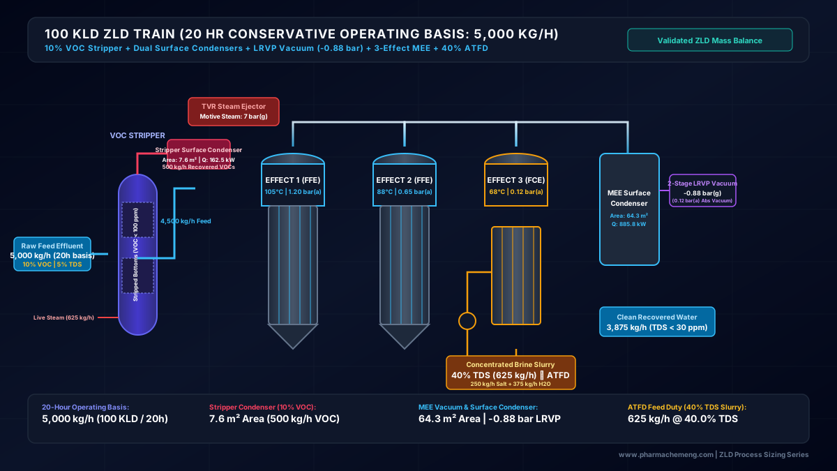
Mechanical Vapor Recompression (MVRE) is a revolutionary energy-saving evaporator technology ideal for concentrating RO reject water () combined with High TDS Mother Liquors ().
# 6.1 MVRE vs. Conventional Multiple Effect Evaporator (MEE) Comparison
  CONVENTIONAL TRIPLE EFFECT MEE vs. MECHANICAL VAPOR RECOMPRESSION (MVRE)

  Triple Effect MEE (Requires Live Steam Boiler):
  [Boiler Steam 1000 kg/h] ──► [Effect 1] ──► [Effect 2] ──► [Effect 3] ──► [Condenser / Cooling Tower]
  * Steam Economy: 2.8 kg water / kg steam (High thermal energy cost)

  Mechanical Vapor Recompression (MVRE - Power Driven):
  ┌────────────────────────────────────────────────────────────────────────┐
  │                                                                        │
  ▼                                                                        │
[Evaporator Vessel] ──(Vapor 100°C)──► [Vapor Compressor Motor 45 kW] ──(Vapor 106.5°C)
  ▲                                           │ (Compressed Vapor as Heating Steam)
  └───────────────────(Heat Transfer)─────────┘
  * Equivalent Steam Economy: 18 - 25 kg water / kg steam equivalent (75% OPEX Reduction!)
# 6.2 MVRE Thermal & Mechanical Sizing Calculations
- Combined MVRE Feed Rate (): High COD Stream A () + RO Reject () = ().
- Feed TDS: .
- Target Concentrated Slurry TDS: .
- Water Evaporation Rate ():
- MVRE Distillate Condensate Recovery: (, ). Recycled for plant washing.
- Concentrated Slurry Flow to ATFD: .
- Vapor Compressor Motor Power Calculation:
- Vapor flow rate: .
- Suction temperature: ().
- Compressor pressure ratio: ( temperature boost to ).
- Isentropic compressor shaft power:
* Adopt ** Heavy-Duty Centrifugal Vapor Fan/Compressor Drive**.
- MVRE Specific Energy Consumption:
- Evaporator Heat Transfer Area (HTA):
- Latent heat of condensation .
- Heat Duty .
- Overall Heat Transfer Coefficient (Falling Film Titanium tubes).
- Temperature difference .
- Required HTA:
# 7. Statutory CPCB Discharge Standards vs. ZLD Reuse Specifications
The DBR must contrast environmental discharge standards against internal factory ZLD water reuse quality targets:
| Water Quality Parameter | CPCB Inland Surface Water Discharge Limits | CPCB On-Land Irrigation Norms | ZLD Cooling Tower Makeup Target | ZLD High Pressure Boiler Feed Target |
|---|---|---|---|---|
| pH | ||||
| Total Suspended Solids (TSS) | ||||
| BOD (at 20°C) | ||||
| Chemical Oxygen Demand (COD) | No standard | |||
| Total Dissolved Solids (TDS) | (RO Permeate) | (Post DM) | ||
| Oil & Grease (O&G) | ||||
| Ammoniacal Nitrogen () | No standard | |||
| Silt Density Index () | Not applicable | Not applicable | ||
| Bio-assay (Fish Survival) | survival in 96 hrs | survival | Not applicable | Not applicable |
# 8. Standard Design Basis Report (DBR) Document Template & Checklist
When submitting a DBR for engineering execution or regulatory approval, format the document into 8 standard sections:
# DESIGN BASIS REPORT (DBR)
## LOW TDS BIOLOGICAL ETP, MVRE & ZERO LIQUID DISCHARGE (ZLD) PLANT
### Project: [Plant Name / 500 KL API Manufacturing Unit]

1. INTRODUCTION & PROJECT OVERVIEW
   1.1 Facility Background & Manufacturing Campaigns
   1.2 Statutory Regulatory Framework (CPCB/SPCB Consent Standards)
   1.3 Battery Limits & Scope of Supply

2. EFFLUENT GENERATION & STREAM SEGREGATION
   2.1 Mass Balance of Process Washes, MLs & Utility Blowdowns
   2.2 Stream Classification Matrix (Stream A - HTDS, Stream B - LTDS, Stream C, Stream D)
   2.3 Effluent Characterization Table (Avg, Max, Design Basis)

3. PROCESS FLOWSHEET ARCHITECTURE & UNIT SELECTION
   3.1 HTDS Solvent Stripper Column & MVRE/ATFD System
   3.2 LTDS Equalization & Primary CPI/DAF Unit
   3.3 LTDS Anoxic Denitrification & Membrane Bioreactor (MBR) System
   3.4 Combined Tertiary High Recovery Reverse Osmosis (RO)

4. DETAILED ENGINEERING SIZING CALCULATIONS
   4.1 Tank Volumes, HRT, and Mixing Power
   4.2 Biological Aeration Kinetics (F/M, MLSS, AOR/SOR, Blower CFM, Membrane LMH)
   4.3 RO Membrane Flux, Osmotic Pressure & Recovery Percentages
   4.4 MVRE Vapor Compressor Power, HTA, and Specific Energy Consumption

5. OVERALL WATER & MASS BALANCE
   5.1 Daily Water Balance Block Flow Diagram (BFD)
   5.2 Solid Waste Generation (Biological Sludge, Primary Sludge, MEE Salt)

6. MATERIALS OF CONSTRUCTION (MOC) MATRIX
   6.1 Tanks & Civil Structures (RCC with FRP/Epoxy Lining)
   6.2 Pumps, Piping & Valves (SS316L, Duplex 2205, PP, HDPE)
   6.3 Heat Exchanger Tubes (Titanium Gr. 2 / Duplex 2205 for MVRE)

7. UTILITY & ELECTRICAL CONNECTED LOAD
   7.1 Power Consumption Summary (KW installed / operating)
   7.2 Steam Consumption (kg/hr at pressure bar)
   7.3 Chemical Dosing Requirements (Caustic, Acid, Coagulant, Anti-scalant)

8. INSTRUMENTATION, CONTROL & ONLINE CPCB TRANSMISSION
   8.1 PLC / SCADA Automation Level
   8.2 Online Effluent Monitoring System (pH, TOC, COD, BOD, Flowmeters)
# 9. Summary Checklist for DBR Approval
Before freezing the ETP/ZLD Design Basis Report for procurement, verify:
- LTDS () and HTDS () streams strictly segregated at source.
- Peak hourly factor () applied to hydraulic pump sizing.
- Biological F/M ratio kept between for stable MBR performance.
- Aeration blowers sized with altitude and ambient temperature correction factors.
- RO recovery rate () validated against membrane projection software.
- MVRE vapor compressor power () and Titanium HTA () verified for chloride corrosion.
- Complete plant water balance closes with mass discrepancy.
- Online CPCB/SPCB data transmission telemetry interfaces included.
# 10. Regulatory Standards & Engineering References
- CPCB India: Charter for Water Recycling and Pollution Control in Bulk Drug Industries.
- US-EPA: 40 CFR Part 439 - Pharmaceutical Manufacturing Point Source Category.
- Metcalf & Eddy: Wastewater Engineering: Treatment and Resource Recovery (5th Edition).
- ISO 14001:2015: Environmental Management Systems — Requirements with Guidance for Use.