# Flow Reactor Hardware, Metallurgy & Utility Sizing Guide: Microreactors, PFRs, CSTR Cascades & Photochemical Cells
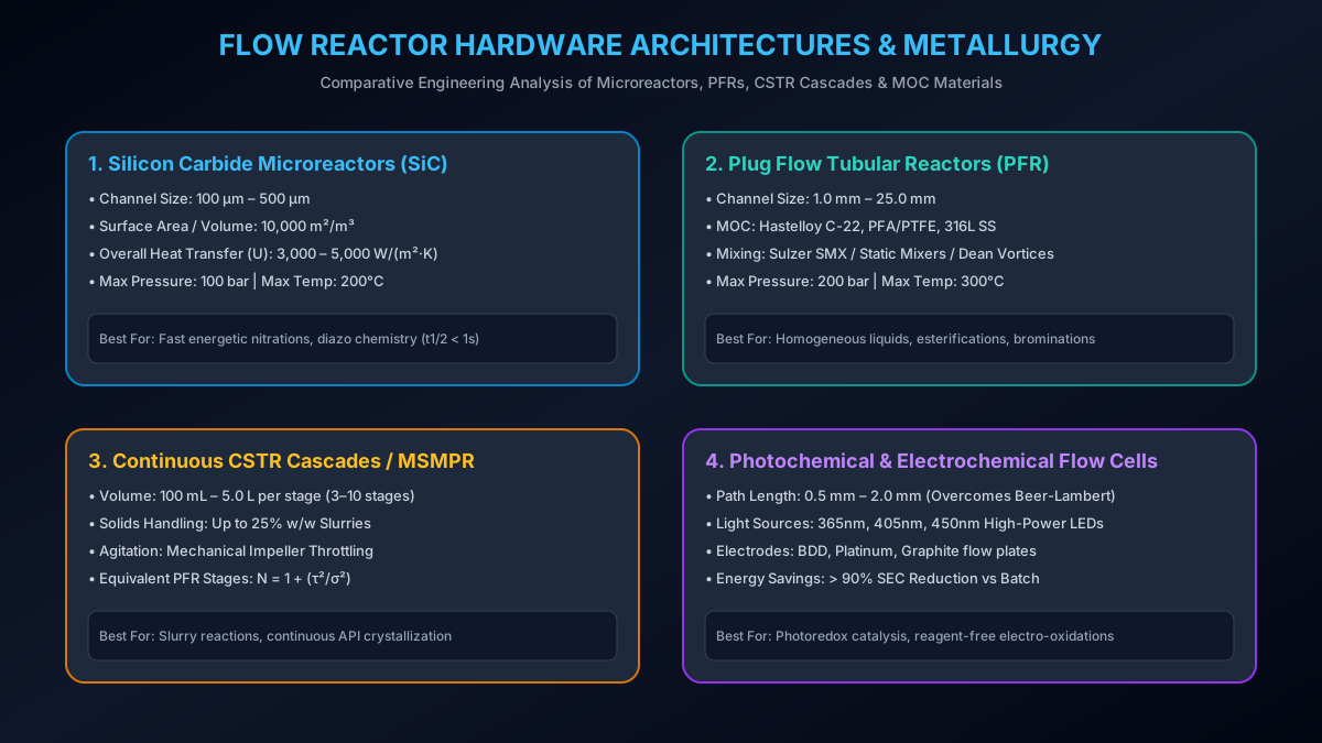
# Executive Summary & Industrial Hardware Scope
The success of continuous flow processing in pharmaceutical and chemical manufacturing depends directly on selecting the proper Flow Reactor Hardware Architecture, Metallurgy / Materials of Construction (MOC), and Thermal Utility Systems. Unlike standard glass-lined or stainless steel batch reactors, continuous flow reactors operate under severe hydrodynamics, high fluid velocities (), intense pressure drops (), and aggressive chemical environments (concentrated acids, halogens, organometallics, and elevated temperatures up to ).
This technical publication presents a comprehensive analysis of five primary flow reactor architectures, evaluates metallurgy and fabrication standards (SiC, Hastelloy C-22, PFA/PTFE, Tantalum, 3D Selective Laser Melting), and establishes first-principles thermal utility sizing equations for Temperature Control Units (TCU).
# 1. Primary Flow Reactor Hardware Architectures
Continuous flow reactors are categorized by their internal geometry, mixing mechanism, phase handling capability, and energy input modality:
                      FLOW REACTOR ARCHITECTURE CLASSIFICATION
 ┌────────────────────────────────────────────────────────────────────────┐
 │ 1. MICROREACTORS (Etched SiC/Glass Channels, 100-500 µm)               │
 │ 2. TUBULAR PLUG FLOW REACTORS (PFR - PFA, Hastelloy, 316L, 1-25 mm)   │
 │ 3. CONTINUOUS STIRRED TANK CASCADE (CSTR Cascades / MSMPR Slurry Flow) │
 │ 4. PACKED-BED FIXED REACTORS (PBR - Heterogeneous Catalysis)           │
 │ 5. PHOTOCHEMICAL & ELECTROCHEMICAL FLOW CELLS (LED Arrays / Electrodes)│
 └────────────────────────────────────────────────────────────────────────┘
# 1.1 Microreactors (Etched Silicon Carbide & Glass)
Microreactors feature sub-millimeter fluid channels () etched into solid blocks of Alpha-grade Silicon Carbide (SiC) or Borosilicate Glass.
                      SILICON CARBIDE (SiC) HEART-SHAPED MIXER
 ┌────────────────────────────────────────────────────────────────────────┐
 │ SURFACE-TO-VOLUME RATIO: A/V = 4 / d_h = 10,000 m²/m³                   │
 │ OVERALL HEAT TRANSFER COEFFICIENT: U = 3,000 - 5,000 W/(m²·K)          │
 ├────────────────────────────────────────────────────────────────────────┤
 │                                                                        │
 │  Fluid A ──┐                                                           │
 │            ├──► [Heart-Shaped Vortex Channel] ──► [Milking Channels] ──► Product
 │  Fluid B ──┘    (Laminar Re-mixing Nodes)        (Isothermal Cooling)  │
 └────────────────────────────────────────────────────────────────────────┘
- Key Advantages: Extremely high surface-to-volume ratio (), overall heat transfer coefficient (), and near-instantaneous mixing ().
- Limitations: Extremely high pressure drop (); vulnerable to particulate channel plugging.
# 1.2 Tubular Plug Flow Reactors (PFR)
Tubular PFRs consist of coiled or linear tubing () fitted with static mixing elements (Sulzer SMX, Kenics, or helical coils) encased inside a shell-and-tube utility heat exchanger.
- Fluid Mechanics: Dean vortices induced by curvature generate radial mixing while suppressing axial dispersion ().
- Primary Use Case: Homogeneous liquid-liquid reactions, nitrations, brominations, and esterifications with residence times from to .
# 1.3 Cascaded Continuous Stirred Tank Reactors (CSTR Cascades / MSMPR)
A CSTR Cascade comprises 3 to 10 miniature stirred vessels ( to volume) connected in series with continuous overflow or inter-stage pumps.
                    3-STAGE CSTR CASCADE FOR SLURRY & CRYSTALLIZATION
 ┌────────────────────────────────────────────────────────────────────────┐
 │ EQUIVALENT PFR STAGES: N_stages = 1 + (τ² / σ²)                        │
 ├────────────────────────────────────────────────────────────────────────┤
 │                                                                        │
 │  Feed A+B ──► [CSTR 1] ──────────► [CSTR 2] ──────────► [CSTR 3] ──► Slurry Output
 │               (Agitator 1)          (Agitator 2)          (Agitator 3) │
 │                Temp: T_1             Temp: T_2             Temp: T_3   │
 └────────────────────────────────────────────────────────────────────────┘
- Key Advantage: Excellent suspension of solid precipitates, slurries, and active pharmaceutical ingredient (API) crystallizations without channel clogging.
- RTD Profile: Approaches ideal plug flow () when stages.
# 1.4 Packed-Bed Reactors (PBR / Fixed-Bed Flow)
PBRs consist of tubular columns filled with solid heterogeneous catalysts (e.g., , , Raney Nickel, or immobilized enzymes).
- Design Equation: Residence time based on Cat-Weight-to-Flow-Rate ratio ():
# 1.5 Photochemical & Electrochemical Flow Cells
- Photochemical Flow Reactors: Thin-walled fluoropolymer tubing coiled around high-intensity narrow-band LED arrays (). The small path length () overcomes the Beer-Lambert light attenuation law ().
- Electrochemical Flow Cells: Parallel-plate flow channels with narrow inter-electrode gaps () yielding high mass transfer rates without supporting electrolyte salts.
# 2. Materials of Construction (MOC) & Metallurgy Matrix
Selecting the appropriate material of construction (MOC) is critical to prevent corrosion, metal leaching, and reactor failure:
| Material of Construction (MOC) | Max Temp Range | Max Operating Pressure | Corrosion Resistance Profile | Thermal Conductivity () | Relative Cost Factor |
|---|---|---|---|---|---|
| Alpha-Grade Silicon Carbide (SiC) | to | Universal (HCl, , , NaOH, Organics) | (High Benchmark) | ||
| Hastelloy C-22 / C-276 | to | Excellent to Chlorides, Wet , Hydrochloric & Formic acids | |||
| PFA / PTFE Fluoropolymers | to | Universal chemical inertness (except molten alkali metal) | (Low Cost) | ||
| Tantalum-Lined Steel | to | Immune to concentrated hot Aqua Regia & | (Ultra Premium) | ||
| Borosilicate Glass 3.3 | to | Excellent visibility; weak against HF & concentrated hot alkali | |||
| 3D-Printed Titanium (Grade 5 SLM) | to | Nitric acid, seawater, pharmaceutical solvents |
# 3. Fabrication & Engineering Standards for Flow Reactor Modules
Industrial flow skids operating in cGMP pharmaceutical environments must comply with international piping and pressure vessel codes:
- ASME B31.3 (Process Piping Code): Dictates minimum wall thickness () for high-pressure flow reactor tubing:
Where is design pressure, is outside diameter, is allowable stress value, and is quality factor.
ISO 1127 / ASME BPE (Bioprocess Equipment Standard): Specifies internal surface roughness (, electropolished) for pharmaceutical contact lines to prevent residue buildup and cross-batch contamination.
ATEX / IECEx Certification: Flow skids containing organic solvents must feature explosion-proof intrinsically safe electronics (Zone 1 / Zone 2, Ex d / Ex ia).
# 4. Temperature Control Unit (TCU) & Thermal Sizing Calculations
The high surface-area-to-volume ratio () of flow reactors enables near-isothermal operation, provided the external Temperature Control Unit (TCU) is sized correctly.
                      TCU THERMAL UTILITY HEAT BALANCE LOOP
 ┌────────────────────────────────────────────────────────────────────────┐
 │ HEAT BALANCE: Q_TCU = Q_reaction + Q_sensible = U · A · ΔT_lm          │
 ├────────────────────────────────────────────────────────────────────────┤
 │                                                                        │
 │  [HIGH-DYNAMIC TCU] ──► (Utility Thermal Fluid) ──► [FLOW REACTOR JACKET]
 │        ▲                                                   │           │
 │        └──────────────── (Return Brine / Oil) ─────────────┘           │
 └────────────────────────────────────────────────────────────────────────┘
# First-Principles Heat Transfer & Utility Equations:
# 1. Heat Duty Requirement ():
# 2. Overall Heat Transfer Coefficient ():
Where is internal fluid heat transfer coefficient, is jacket utility coefficient, is thermal conductivity of reactor wall, and is fouling factor.
# 3. Internal Nusselt Correlation ():
# Worked Numerical Example: TCU Sizing for a SiC Microreactor
# Process Input Data:
- Reaction: Fast exothermic nitration ().
- Flow Rate: .
- Reactant Concentration: .
- Feed Inlet Temp: ; Target Outlet Temp: (Isothermal).
- Reactor Metrics: Silicon Carbide block (, ).
# Step 1: Calculate Reaction Heat Generation ()
# Step 2: Calculate Required Log-Mean Temperature Difference ()
Since , , so .
# Step 3: Select TCU Utility Fluid Temperature ()
To remove of heat isotropically, the TCU utility oil must circulate at:
Engineering Takeaway: Thanks to SiC's massive heat transfer capacity (), an intense exothermic reaction is safely controlled using utility fluid just below the process setpoint. In a 5,000 L batch vessel, the same reaction would require cryogenic brine at and risk thermal runaway.
# 5. Flow Reactor Pressure Drop () Sizing Equations
Pumping fluids through narrow micro-channels generates substantial friction pressure drop (). Pumping systems must be sized to prevent over-pressurization:
Where is Darcy friction factor:
- Laminar Flow ():
- Turbulent Flow (): (Blasius Equation)
# Applicable Engineering Standards & Codes
- ASME B31.3: Process Piping Code for Pressure Safety Compliance
- ASME BPE: Bioprocess Equipment Standard for Surface Finish and Sanitary Clamps
- ISO 1127: Stainless Steel Tubes - Dimensions, Tolerances and Conventional Masses per Unit Length
- DIN 4754: Heat Transfer Plants Operating with Organic Thermal Liquids (TCU Safety)