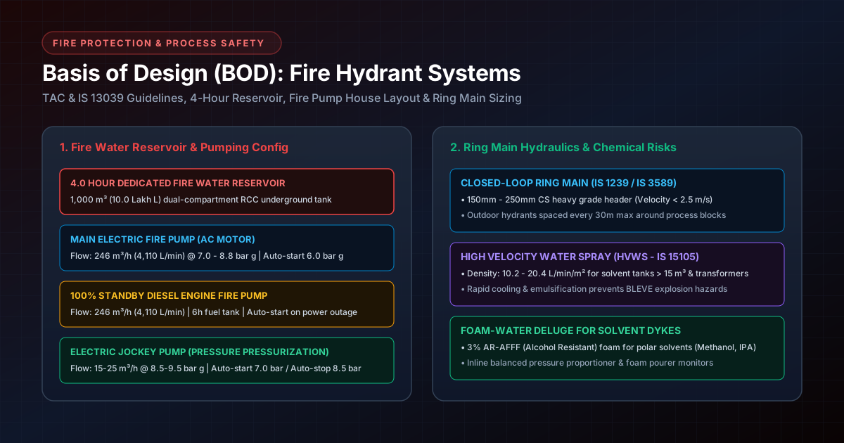
# Basis of Design (BOD) for Fire Hydrant Systems in Chemical & Pharma Plants: TAC/IS Guidelines, Fire Pump House Layout & Ring Main Sizing
# Executive Summary & Regulatory Framework
In Indian Active Pharmaceutical Ingredient (API), specialty chemical, and fine chemical manufacturing plants, fire is the single largest catastrophic risk. Handling thousands of liters of highly volatile Class A/B flammable solvents (Methanol, Toluene, Acetone, IPA, Ethyl Acetate, THF), combustible bulk powders, and exothermic reactions requires a high-capacity, instantly responsive Fire Water Hydrant & Spray Deluge Network.
Under Indian statutory regulations and industrial insurance frameworks, fire protection design is strictly governed by:
- Tariff Advisory Committee (TAC) Fire Protection Manual (Section 3): The foundational benchmark for hydrant ring main hydraulics, pump capacities based on hazard risk, and pipe velocity limits.
- IS 13039 (2014): Code of Practice for Provision and Maintenance of Water Supplies for Fire Fighting in Industrial Premises.
- National Building Code of India (NBC) 2016 - Part 4 (Group J): Fire and Life Safety requirements for High Hazard Industrial Occupancies.
- IS 3844 (1989): Code of Practice for Installation and Maintenance of Internal Fire Hydrants and Hose Reels on Premises.
- OISD-STD-116 & OISD-STD-117: Fire Protection Facilities for Petroleum Refineries, Chemical Process Units, and Solvent Depots.
This technical publication presents a validated engineering case study for a 400 KL API Facility (4 × 100 KL Reactor Blocks, RM/FG Warehouses, Solvent Tank Farm) covering fire load density math, pump house sizing, 2,400 m³ reservoir design, ring main pipe sizing hydraulics, and full piping/fitting material specifications.
# 1. Plant Case Study & Fire Load Density Calculations
# 1.1 Facility Profile: 400 KL API Manufacturing Plant
- Process Infrastructure: Four (4) Independent Manufacturing Reactor Blocks (Blocks 1 to 4) with 100 KL reactor volume each (Total 400 KL reaction capacity, 4,800 m² total reactor area).
- Material Storage Infrastructure:
- Raw Material (RM) Warehouse (2,000 m² floor area): Bulk powder drums, packaging materials, solvent day drums.
- Finished Goods (FG) Warehouse (2,000 m² floor area): Bulk API drums, corrugated outer cartons, wooden/HDPE pallets.
- Bulk Solvent Tank Farm (2,500 m² dyke area): 500 KL total solvent storage (Methanol, Toluene, Acetone, IPA).
- Total Built-up / Covered Fire Risk Area: 11,300 m² (exceeds 10,000 m² statutory high-hazard threshold).
# 1.2 Fire Load Density () Math & Hazard Classification
Fire pump capacities must NEVER be arbitrarily guessed. Engineers calculate the Fire Load Density for each plant block using:
Where:
- = Mass of combustible material stored in the zone (kg).
- = Net calorific value of material (MJ/kg or Mcal/kg).
- = Floor area of the fire compartment (m²).
# Fire Load Breakdown & Statutory Risk Validation:
| Plant Zone | Combustible Inventory & Calorific Value () | Floor Area () | Fire Load Density () | Hazard Category (NBC 2016 / TAC) |
|---|---|---|---|---|
| Reactor Blocks 1 to 4 (Each) | 100 KL reaction mass + 20 MT solvent (42.5 MJ/kg) | 1,200 m² each | 2,850 MJ/m² (680 Mcal/m²) | High Hazard Category C |
| Raw Material Warehouse | 50 MT powders (17.5 MJ/kg) + 10 MT solvent drums | 2,000 m² | 1,850 MJ/m² (442 Mcal/m²) | High Hazard Category B |
| Finished Goods Warehouse | 30 MT API powder + 25 MT wooden/paper packaging | 2,000 m² | 1,420 MJ/m² (339 Mcal/m²) | High Hazard Category B |
| Bulk Solvent Tank Farm | 500 KL flammable solvents (30.0 - 42.5 MJ/kg) | 2,500 m² | 5,200 MJ/m² (1,243 Mcal/m²) | Extreme Hazard (Category C) |
# 2. Validation of Fire Load vs Pumping Capacity & Pump House Sizing
# 2.1 Code Validation (TAC Section 3 Table 2 & IS 13039 Table 2):
Per TAC Manual Section 3 and IS 13039:2014 Table 2, for High Hazard Category C chemical occupancies with covered floor area exceeding 10,000 m² (our plant is 11,300 m²), the Minimum Statutory Fire Water Pumping Capacity is 600 m³/h (10,000 L/min).
# Hydraulic Flow Demand Calculation:
- Hydrant Hose Stream Demand:
For High Hazard Category C occupancies, TAC mandates the simultaneous operation of 8 Double-Headed Outdoor Hydrants (IS 908). Each nozzle stream discharges at 570 L/min:
- High Velocity Water Spray (HVWS) Deluge Demand:
Protecting the largest single 100 m³ solvent storage tank (vessel surface area 150 m² at discharge density 10.2 L/min/m²):
- Total Combined Peak Water Demand:
# 2.2 4-Hour Dedicated Fire Water Storage Reservoir Sizing:
High hazard chemical plants mandate a minimum of 4.0 Hours continuous water supply at maximum combined flow (600 m³/h):
- Structure: Dual-compartment Reinforced Cement Concrete (RCC) underground reservoir (1,200 m³ per compartment) with equalizer motorized valves.
- Dedicated Suction Stubs: Utility water suction pipes are installed 1.5 meters above the reservoir floor, physically reserving the bottom 2,400 m³ exclusively for fire pumps.
# 2.3 Fire Pump House Equipment Configuration & DG Power:
                  FIRE PUMP HOUSE LOCATION & ZONING CLEARANCE
 ┌────────────────────────────────────────────────────────────────────────────────────────┐
 │ SAFE LOCATION: Minimum 30.0m to 60.0m Clear Distance from Hazardous Blocks            │
 ├────────────────────────────────────────────────────────────────────────────────────────┤
 │                                                                                        │
 │  [4 × 100KL REACTOR BLOCKS]               [500 KL SOLVENT TANK FARM]                   │
 │          ▲                                           ▲                                 │
 │          │ (45m Safety Distance)                     │ (60m Safety Zone)               │
 │          ▼                                           ▼                                 │
 │ ┌──────────────────────────────────────────────────────────────────────────────────┐   │
 │ │ FIRE PUMP HOUSE (NON-HAZARDOUS AREA)                                             │   │
 │ │ • 2 × Electric Main Pumps (300 m³/h each) | 1 × Standby Diesel Pump (600 m³/h)   │   │
 │ │ • 2 × Electric Jockey Pressurization Pumps (30 m³/h each)                       │   │
 │ └──────────────────────────────────────────────────────────────────────────────────┘   │
 └────────────────────────────────────────────────────────────────────────────────────────┘
| Equipment | Quantity | Rated Flow | Discharge Pressure | Power Driver & Operating Logic |
|---|---|---|---|---|
| Main Electric Fire Pumps | 2 Units | 300 m³/h (5,000 L/min) each | 8.8 bar g | Electric Motor driven (185 kW each), running in parallel (600 m³/h total). Auto-start at 6.0 bar g; manual stop. |
| Standby Diesel Fire Pump | 1 Unit | 600 m³/h (10,000 L/min) | 8.8 bar g | 100% Redundant Diesel Engine (380 kW) with 8h day tank. Auto-starts at 5.0 bar g or on grid failure; manual stop. |
| Jockey Pressurization Pumps | 2 Units | 30 m³/h (500 L/min) each | 9.5 bar g | Electric Motor driven (18.5 kW). Auto-starts at 7.0 bar g; auto-stops at 8.5 bar g to maintain ring main pressure. |
# Emergency Diesel Generator (DG) Power Backing:
- Auto-Transfer Switch (ATS): Electric fire pumps are connected directly to the plant DG Emergency Bus. Upon grid trip, ATS switches power supply to emergency DG power within 15 to 30 seconds.
- Fire-Surv Cabling (IEC 60331): Power cables use Mineral Insulated / MICA Tape insulated Copper Cables rated to withstand 950°C for 3.0 Hours without loss of electrical continuity.
# 3. Ring Main Hydraulics & Pipe Sizing Calculation
# 3.1 Main Ring Header Diameter Calculation:
Water velocity () inside the ring main header must not exceed 2.2 m/s during peak firefighting flow (600 m³/h = 0.1667 m³/s):
- Header Pipe Selection: Select standard 350 mm (14-inch) NB Heavy Grade Carbon Steel Pipe for the primary outer ring main.
- Distribution Sub-Headers: 250 mm (10-inch) NB headers looping around individual reactor blocks; 100 mm (4-inch) NB branch pipes to individual hydrants.
# 4. Piping, Valves & Fittings Engineering Specifications
To ensure structural survival and zero corrosion leakage over a 30-year plant operational life, the fire protection network adheres to the following material specifications:
# 4.1 Detailed Material Specifications Table:
| Piping Component | Standard / Code | Material Specification | Pressure Rating / Class | End Connection & Coating |
|---|---|---|---|---|
| Aboveground Ring Main Pipe | IS 3589 / IS 1239 | Carbon Steel ERW / Seamless (Grade Fe 410 / YST 240) | Heavy Class (PN 16) | Beveled welded / Flanged (ANSI B16.5 Class 150). Red PU paint (IS 5 Shade 536). |
| Underground Ring Main Pipe | IS 3589 / IS 10221 | Carbon Steel ERW with external 3LPE / Coal Tar Enamel wrapping | Heavy Class (PN 16) | Welded joints with 3LPE field heat-shrink sleeves + cathodic protection. |
| Sectional Isolation Valves | IS 14846 / BS 5163 | Cast Steel (ASTM A216 Gr. WCB) OS&Y Gate Valve with SS 316 trim | Class 150 (PN 16) | Flanged end, Post Indicator Valve (PIV) with tamper limit switch. |
| Non-Return (Check) Valves | IS 5312 / BS 1868 | Cast Steel Swing Check Valve with SS 316 trim & synthetic rubber seat | Class 150 (PN 16) | Flanged end, non-slam hydraulic dampener. |
| Double-Headed Hydrants | IS 908 | Gunmetal (BS EN 1982 CuSn5Zn5Pb5) or Stainless Steel (SS 316) | PN 16 (16 bar test) | 75 mm NB flanged inlet, dual 63 mm female instantaneous outlets. |
| Fire Hoses & Nozzles | IS 636 Type B / IS 903 | Synthetic Rubber Lined (RRL) Hose with SS 316 instantaneous male/female couplings | 21 bar burst pressure | Two 15 m hoses per hose box + 63 mm multipurpose jet/spray nozzle. |
# 5. Summary of Official Regulatory & Engineering Standards
| Standard / Regulatory Code | Issuing Body | Scope & Engineering Application |
|---|---|---|
| TAC Fire Protection Manual | Tariff Advisory Committee | Hydraulic Sizing Benchmark: Section 3 Table 2 guidelines for sizing ring mains, pump capacity based on hazard class and floor area. |
| IS 13039 (2014) | Bureau of Indian Standards (BIS) | Industrial Fire Water Supplies: Table 2 standards for fire fighting water supplies in high hazard industrial premises. |
| NBC 2016 - Part 4 | BIS / Ministry of Housing | National Building Code: Fire and life safety requirements for Group J High Hazard Industrial Occupancies. |
| IS 3589 / IS 1239 | Bureau of Indian Standards (BIS) | Steel Pipe Specification: Carbon steel pipes for water and sewage (Heavy Class ERW/Seamless). |
| IS 10221 | Bureau of Indian Standards (BIS) | Underground Pipe Coating: Code of practice for coating and wrapping of underground mild steel pipelines. |
| IS 908 & IS 903 | Bureau of Indian Standards (BIS) | Fire Hydrant Hardware: Specifications for double-headed fire hydrants, hose couplings, nozzles, and branch pipes. |
| IS 15105 (2002) | Bureau of Indian Standards (BIS) | Fixed Water Spray Systems: Design and installation of High Velocity (HVWS) and Medium Velocity (MVWS) water spray systems. |
| OISD-STD-116 / 117 | Oil Industry Safety Directorate | Process Unit Protection: Fire protection standards for chemical process units, solvent storage, and LPG facilities. |
| IEC 60331 | International Electrotechnical Commission | Fire-Surv Cable Standard: Fire resistance test for electric power cables at 950°C for 3 hours. |