# Advanced Reactive System Screening Tool (ARSST) in Hazard Identification: Low-Phi Calorimetry, Gas Evolution & DIERS Emergency Vent Sizing
The Advanced Reactive System Screening Tool (ARSST)—developed by Fauske & Associates under the Design Institute for Emergency Relief Systems (DIERS)—is a specialized benchtop calorimeter designed for rapid thermal hazard screening and quantitative emergency pressure relief sizing (PSV and Rupture Disk sizing).
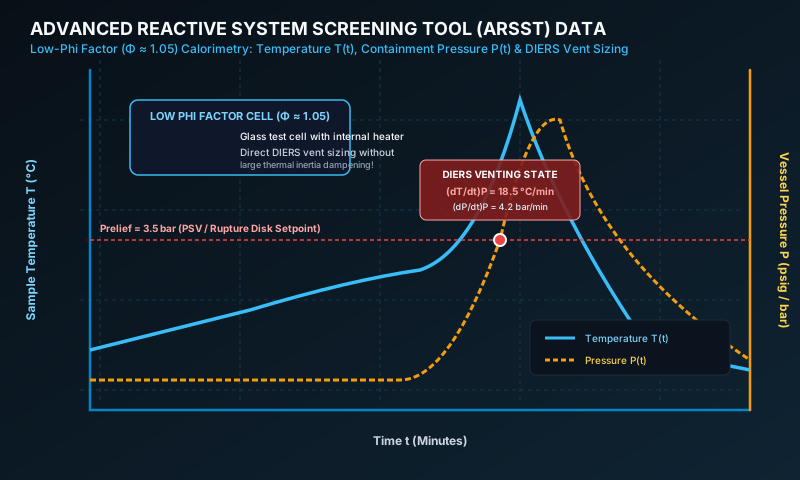
Unlike conventional Accelerating Rate Calorimetry (ARC), which requires heavy metal bombs resulting in high thermal inertia (), the ARSST utilizes an open glass test cell suspended in a pressurized vessel, achieving an extraordinarily low thermal inertia factor (). This low- factor allows direct, uncorrected measurement of runaway self-heating rates , gas generation rates (), and pressure rise rates required for DIERS Leung vent sizing calculations.
# 1. Operating Principles & Instrument Architecture
The ARSST system consists of a spherical open glass test cell containing the liquid sample (), surrounded by a lightweight internal electric heater belt. The glass cell sits inside a stainless steel high-pressure containment vessel rated to ().
# Key Features of ARSST Operation
- Pressure Equalization System: The glass cell is open to the internal containment vessel volume. Nitrogen backpressure () is applied before testing to prevent low-temperature boiling of volatile solvents, suppressing evaporative masking.
- Polynomial Heating Mode: The internal heater applies a constant or polynomial power input to heat the sample at a fixed baseline rate (). When an exothermic reaction occurs, the self-heating rate superimposes on the background ramp.
- Low Phi-Factor (): Because the glass cell wall is thin () and insulation is minimal, almost all chemical heat generation goes directly into raising the sample temperature:
# 2. Governing Equations & Mathematical Data Integration
# A. Power & Energy Balance in ARSST
The total non-isothermal heat balance for the ARSST sample cell during a thermal run is:
Because the background heater power is calibrated against thermal losses prior to exotherm onset:
The net measured self-heating rate directly mirrors the true chemical self-heating rate:
# B. Gas Evolution Rate Integration ()
For non-condensable gas-generating decomposition reactions, the total moles of gas evolved and volumetric gas generation rate ( or ) are derived from the containment vessel pressure rise rate :
where is the free gas headspace volume inside the containment vessel ().
# 3. Characterization of Runaway Flow Regimes: Diagnostics
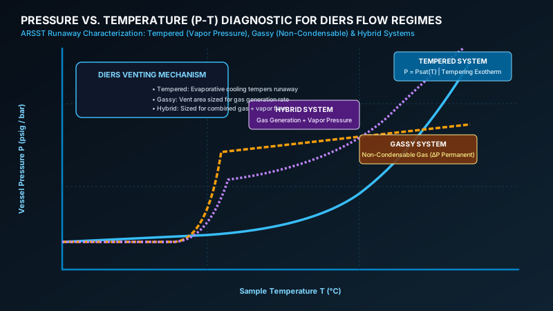
To apply DIERS emergency relief sizing equations correctly, the runaway mechanism must be categorized into one of three distinct thermodynamic regimes using the ARSST Pressure versus Temperature () plot.
# Comparison of DIERS Flow Regimes
| Flow Regime | Physical Mechanism | Curve Characteristics | Relief Sizing Philosophy |
|---|---|---|---|
| Tempered System | Reaction involves a volatile solvent/reagent. Vaporization tempers runaway temperature. | Follows Antoine vapor pressure curve . Pressure drops back to upon cooling. | Sized using Leung Tempered Two-Phase Flow Model. Sizing governed by latent heat . |
| Gassy System | Decomposition generates non-condensable gases () with negligible solvent volatility. | Linear or step pressure increase. Permanent pressure rise remains after cooling. | Sized using DIERS Gassy Model. Sizing governed by max gas generation rate . |
| Hybrid System | Combined non-condensable gas generation AND volatile solvent vapor pressure. | Initial gassy pressure step followed by steep exponential vapor pressure surge. | Sized using DIERS Hybrid Model (combined gas + vapor mass flow). |
# 4. DIERS Emergency Relief Vent Sizing & Pressure Trajectory
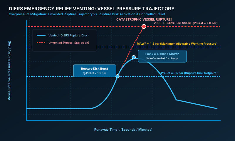
When an emergency pressure relief valve or rupture disk opens, the pressure inside the reactor is governed by the dynamic discharge capacity through the vent pipe.
# A. Leung vs. Fauske Equations for Tempered Two-Phase Venting
In DIERS methodology, two primary formulations are used to calculate the required vent area for tempered (vapor-controlled) two-phase runaway reactions depending on whether exact Clausius-Clapeyron thermodynamics or allowable overpressure approximations are used:
# Formulation 1: Leung Differential Equation (Exact Clausius-Clapeyron Form)
For a tempered runaway reaction, the required vent area per unit vessel volume () evaluated at the relief pressure setpoint is expressed as:
where:
- is the homogeneous two-phase mixture density inside the vessel at relief setpoint ().
- is the flashing two-phase critical mass flux through the vent pipe ().
- is the ARSST self-heating rate evaluated at the temperature corresponding to relief setpoint pressure ().
- is the absolute temperature at relief setpressure ().
- is the specific heat capacity of the liquid reaction mass ().
- is the specific volume change upon vaporization ().
# Formulation 2: Fauske Integrated Nomograph Equation (Allowable Overpressure Form)
When an allowable overpressure (typically above set pressure) is specified for hand calculation:
where:
- is the total mass of the reaction mixture in the vessel ().
- is the latent heat of vaporization of the volatile solvent ().
- is the fractional overpressure above set pressure ().
# B. DIERS Vent Area Equation for Gassy Systems
For non-tempered gassy decompositions, tempering does not occur, and relief must discharge gas fast enough to prevent vessel overpressurization above maximum allowable working pressure ():
where:
- is the ideal gas sonic choke flux ():
- is the maximum mass-specific gas evolution rate () extracted directly from ARSST pressure data.
# 5. Sample Analysis Illustration & Step-by-Step Result Derivation
To demonstrate how ARSST data directly yields an industrial emergency pressure relief vent sizing result, consider a case study of an Aqueous Diazonium Salt Decomposition in a () batch vessel.
# A. ARSST Experimental Parameters
- Sample Mass (): ().
- Containment Free Volume (): ().
- Pad Pressure (): ().
- Measured Phi-Factor (): (negligible thermal dampening).
- Target PSV Relief Setpoint (): ().
- MAWP of Plant Reactor: ().
+---------------------------------------------------------------------------------------+
|                    ARSST SIGNAL INTEGRATION & VENT SIZING FLOW                        |
+---------------------------------------------------------------------------------------+
| 1. Log P-T Diagnostic: P increases by 18.2 bar and STAYS elevated upon cooling.       |
|    --> FLOW REGIME DIAGNOSIS = GASSY SYSTEM (Non-Condensable N2 Gas Generation).      |
| 2. Read ARSST Data at Prelief = 3.50 bar:                                             |
|    --> Temp at Relief Setpoint: Trelief = 92.0 °C (365.15 K)                          |
|    --> Pressure Rise Rate:      (dP/dt)max = 4.20 bar/min (7,000 Pa/s)                 |
+---------------------------------------------------------------------------------------+
                                           |
                                           v
+---------------------------------------------------------------------------------------+
| 3. Specific Gas Rate: Qgas/ms = (Vcont / Pstd) × (dP/dt) / ms                         |
|                       Qgas/ms = 1.85 × 10⁻⁴ m³/(kg·s)                                 |
| 4. Sonic Choke Flux:  Ggas = 185.4 kg/(m²·s)                                          |
| 5. Vent Area Ratio:   A/V = (1 / 185.4) × 1020 kg/m³ × (1.85 × 10⁻⁴) = 0.001018 m²/m³   |
+---------------------------------------------------------------------------------------+
# B. Step-by-Step Emergency Vent Sizing Result Derivation Table
| Derivation Step | Parameter | Mathematical Value | Physical & Safety Interpretation |
|---|---|---|---|
| Step 1 | Flow Regime Diagnosis | GASSY SYSTEM | Permanent non-condensable gas. Evaporative cooling cannot stop pressure rise. |
| Step 2 | Relief State Pressure | () | Setpoint of emergency rupture disk device. |
| Step 3 | Relief State Temperature | () | Temperature of reaction mass when relief setpoint is reached. |
| Step 4 | Gas Evolution Rate | Maximum volumetric gas generation per unit mass derived from ARSST . | |
| Step 5 | Sonic Gas Vent Flux | Maximum discharge mass flow capacity through relief nozzle. | |
| Step 6 | Required Area Ratio () | () | DIERS required relief vent area per cubic meter of batch liquid. |
| Step 7 | Final Vent Diameter () | FINAL PLANT DECISION: Install a ( NB) rupture disk on the reactor. |
# 6. Where to Use ARSST in Process Safety Engineering
- DIERS Emergency Relief Valve & Rupture Disk Sizing: Provide primary experimental inputs for relief valve nozzle and rupture disk orifice sizing for reactors, distillation columns, and storage vessels.
- Screening Reactive Chemical Incompatibilities: Rapidly evaluate binary compatibility matrices (e.g., acid + base, oxidizer + solvent, catalyst + impurity) within .
- Effluent Handling System Sizing: Sizing quench tanks, knockout drums, and flare stacks based on two-phase vent discharge rates.