# Industrial Crystallization Engineering: Modes, Stages, Solute Fate Dynamics, Cooling & Agitation Mechanics, Aspen Plus PSD Simulation & PAT Instrumentation
# Executive Summary & Technical Scope
In pharmaceutical Active Pharmaceutical Ingredient (API) production, fine chemical synthesis, and specialty agrochemical processing, Crystallization is the paramount unit operation. It simultaneously serves as the primary purification process ( chemical purity) and the final solid-state particle engineering step that establishes Critical Quality Attributes (CQAs): Particle Size Distribution (PSD ), Polymorphic Form (crystalline phase lattice), Particle Morphology (habit/aspect ratio), and Residual Solvent Levels.
Sub-optimal crystallization control leads to broad bimodal PSDs, severe filtration/drying delays in Agitated Nutsche Filter Dryers (ANFDs), impurity occlusion within crystal lattices, and un-predictable drug dissolution kinetics.
This comprehensive chemical engineering treatise covers:
- 5 Industrial Modes of Crystallization (Cooling, Anti-Solvent, Evaporative, Reactive/Precipitation, Melt) with process flow illustrations.
- The 5 Sequential Stages of Crystallization & Solute Fate Analysis (Tracking solute molecules across liquid mother liquor vs. solid crystal interfaces).
- Cooling Profiles & Agitation Dynamics (Cubic vs. Linear cooling, Meta-Stable Zone Width (MSZW), impeller tip speed, secondary nucleation, and boundary layer diffusion).
- Aspen Plus Population Balance Simulation (Cryst Block Worked Example) & Manual Kinetics Cooling Ramp Worked Calculation (Predicting average size and yield from cooling rate kinetics).
- Analytical PAT & Offline Instrumentation (FBRM, PVM, ATR-FTIR, Raman, Malvern Laser Diffraction, PXRD).
- Governing Chemical Engineering Equations Summary Table.
# 1. Classification & Industrial Modes of Crystallization
Crystallization requires driving a liquid solution into a thermodynamic state of Supersaturation (). Depending on the temperature-solubility relationship of the solute-solvent system, five distinct industrial modes are utilized:
                         INDUSTRIAL CRYSTALLIZATION MODES
  ┌───────────────────┐  ┌───────────────────┐  ┌───────────────────┐  ┌───────────────────┐
  │  Cooling          │  │  Anti-Solvent     │  │  Evaporative      │  │  Reactive / Precip│
  │  Crystallization  │  │  Crystallization  │  │  Crystallization  │  │  Crystallization  │
  └─────────┬─────────┘  └─────────┬─────────┘  └─────────┬─────────┘  └─────────┬─────────┘
            │                      │                      │                      │
  • High positive dC*/dT   • High solubility in   • Flat solubility      • Rapid chemical
  • Steeper slope         • primary solvent;     • curve (dC*/dT ~ 0)   • reaction forms
  • Thermally controlled  • zero in anti-solvent • Water / Inorganic    • insoluble product
# 1.1 Cooling Crystallization
- Mechanism: Temperature reduction decreases the equilibrium solubility () of the solute in the solvent.
- Ideal System: Solutes demonstrating a steep positive solubility curve (), such as API intermediates in ethanol, acetone, or toluene.
- Equipment: Glass-Lined Steel (MSGL) or Hastelloy reactors fitted with external utility jackets, internal cooling coils, and low-shear hydrofoil agitators.
# 1.2 Anti-Solvent (Precipitation) Crystallization
- Mechanism: Addition of a miscible second liquid ("anti-solvent") in which the solute has near-zero solubility. This dramatically drops the overall solvent mixture capacity, generating intense supersaturation.
- Ideal System: Solutes with high thermal stability or those where thermal cooling is insufficient (flat solubility curve). Example: Adding Water to an API dissolved in DMF or Isopropanol.
- Operational Requirement: Dosing anti-solvent via submerged dip-tubes positioned directly in high-shear agitator zones to prevent localized primary nucleation spikes.
# 1.3 Evaporative Crystallization
- Mechanism: Removal of solvent vapor via heat input under vacuum or atmospheric pressure, concentrating the remaining solute above its solubility limit.
- Ideal System: Solutes exhibiting flat or retrograde solubility curves (), such as Sodium Chloride () or Ammonium Sulfate in water.
- Equipment: Forced Circulation (FC) Crystallizers, Draft Tube Baffled (DTB) Evaporators, and Oslo Surface-Cooled Crystallizers.
# 1.4 Reactive / Precipitation Crystallization
- Mechanism: Two soluble liquid reactants are mixed to undergo a rapid chemical reaction, producing an insoluble product salt or compound that immediately precipitates out at high supersaturation ().
- Ideal System: Acid-base neutralization salts (e.g., Hydrochloride salt formation: ).
- Challenge: Extremely high local supersaturation generates ultra-fine, amorphous, or un-filterable needle crystals. Requires high-shear inline rotor-stator mixers.
# 1.5 Melt Crystallization
- Mechanism: Separation of high-purity organic substances directly from their molten liquid phase without using organic solvents.
- Ideal System: Isomer separation (e.g., Para-xylene / Meta-xylene, Isocyanates, Monomers). Operates as Falling Film or Static Crystallization.
# Comparison Matrix of Crystallization Modes
| Mode | Primary Driving Force | Energy Source | Typical Yield | Final PSD Range () | Main Advantage | Main Risk |
|---|---|---|---|---|---|---|
| Cooling | (Thermal Drop) | Jacket Cooling Utility | Excellent PSD control; high purity | Encrustation on cold jacket walls | ||
| Anti-Solvent | Composition Shift | Metering Dosing Pump | Low thermal exposure; fast yield | Localized un-controlled nucleation | ||
| Evaporative | Solvent Boiling / Mass Loss | Steam / Thermal Oil | High throughput; flat solubility systems | Thermal degradation; heavy scaling | ||
| Reactive | Chemical Synthesis | Reaction Free Energy | High single-pass conversion | Fine un-filterable needles & amorphous traps | ||
| Melt | Solid-Liquid Phase Equilibrium | Refrigeration / Heating | N/A (Melt Layer) | Zero Solvent Use; high purity () | High energy input; solid handling complexity |
# 2. The 5 Core Stages of Crystallization & Solute Fate Analysis
To master particle size and purity, process engineers must track the Solute Fate (where solute molecules reside and how they assemble) across five consecutive crystallization stages:
                             SOLUTE FATE & PHASE EVOLUTION
  ┌──────────────────┐   ┌──────────────────┐   ┌──────────────────┐   ┌──────────────────┐
  │ Stage 1:         │   │ Stage 2:         │   │ Stage 3:         │   │ Stage 4:         │
  │ Unsaturated Soln │──>│ Metastable Zone  │──>│ Nucleation       │──>│ Crystal Growth   │
  │ Solute: Dispersed│   │ Solute: Molecular│   │ Solute: Critical │   │ Solute: Lattice  │
  │ Solvated Ions    │   │ Clusters / Embryo│   │ Nuclei Clusters  │   │ Incorporation    │
  └──────────────────┘   └──────────────────┘   └──────────────────┘   └──────────────────┘
# Stage 1: Unsaturated Solution State
- Thermodynamic State: ().
- Liquid Phase Fate: Solute molecules exist as fully isolated, solvated monomers or small transient dimers surrounded by solvent shells. Free energy of dissolution is negative ().
- Solid Phase Fate: No solid phase exists. Any added seed crystal will dissolve.
# Stage 2: Metastable Zone (Supersaturated Pre-Nucleation)
- Thermodynamic State: ().
- Liquid Phase Fate: Solute molecules overcome solvation energy to form dynamic sub-critical molecular clusters (embryos) (). Clusters continuously form and redissolve.
- Solid Phase Fate: No spontaneous bulk primary nucleation occurs. However, added seed crystals remain stable and grow smoothly without generating secondary fines.
# Stage 3: Nucleation (Primary & Secondary)
- Thermodynamic State: () OR secondary nucleation triggered by mechanical agitation contact.
- Liquid Phase Fate: Molecular clusters achieve Critical Radius (). The free energy barrier is overcome:
- Solid Phase Fate: Stable solid nuclei are generated (). In Primary Homogeneous Nucleation, pure solute clusters collapse into crystalline unit cells. In Secondary Nucleation, existing seed crystals shed tiny micro-crystallites due to fluid shear and impeller collision.
# Stage 4: Crystal Growth & Face Incorporation
- Thermodynamic State: Supersaturation drops as growth consumes solute ().
- Liquid Phase Fate: Solute molecules diffuse across the liquid boundary layer (thickness ) toward the growing crystal face. Solute concentration drops from bulk to interface concentration .
- Solid Phase Fate: Solute molecules adsorb onto crystal faces, surface-diffuse, and integrate into growth steps/kinks (BCF Screw Dislocation / Birth-and-Spread Model). Impurity molecules are rejected by the strict crystalline lattice geometry unless surface concentration is excessively high.
# Stage 5: Ostwald Ripening & Polymorphic Phase Transition
- Thermodynamic State: Near equilibrium ().
- Liquid Phase Fate: Small micro-fines () possess higher chemical potential and solubility (Gibbs-Thomson Effect). Fines dissolve into the liquid phase, creating localized supersaturation that deposits onto larger crystals.
- Solid Phase Fate: Overall particle count decreases while average increases. Metastable polymorphic forms (e.g. Form II) dissolve and re-crystallize into the thermodynamically stable Form I lattice.
# Comprehensive Solute Fate Summary Table
| Stage | Liquid Phase Solute Fate | Solid Phase / Lattice Fate | Impurity Fate | Engineering Control Lever |
|---|---|---|---|---|
| 1. Unsaturated | Solvated monomers in solution | Zero solid present | Uniformly dissolved | Maintain during raw material charge |
| 2. Metastable Zone | Dynamic sub-critical clusters () | Stable growth on added seed bed | Uniformly dissolved | Controlled cooling / anti-solvent metering within MSZW |
| 3. Nucleation | Solute clusters exceed critical radius | Solid nuclei born () | Potential inclusion in rapid primary nuclei | Charge seed bed (); limit max |
| 4. Crystal Growth | Mass transfer across film diffusion layer | Layer-by-layer lattice integration | Rejection from lattice (Purity boost) | Maintain steady, low supersaturation () |
| 5. Ripening/Polymorph | Fines dissolve via Gibbs-Thomson effect | Large crystals grow; polymorph converts | Trapped surface mother liquor released | Thermal aging hold () at slurry end-temp |
# 3. Impact of Cooling Profiles & Agitation Dynamics on PSD
Particle Size Distribution (PSD) is overwhelmingly controlled by two plant operating parameters: Cooling Temperature Profile and Agitation Shear Energy.
# 3.1 Cooling Temperature Profiles
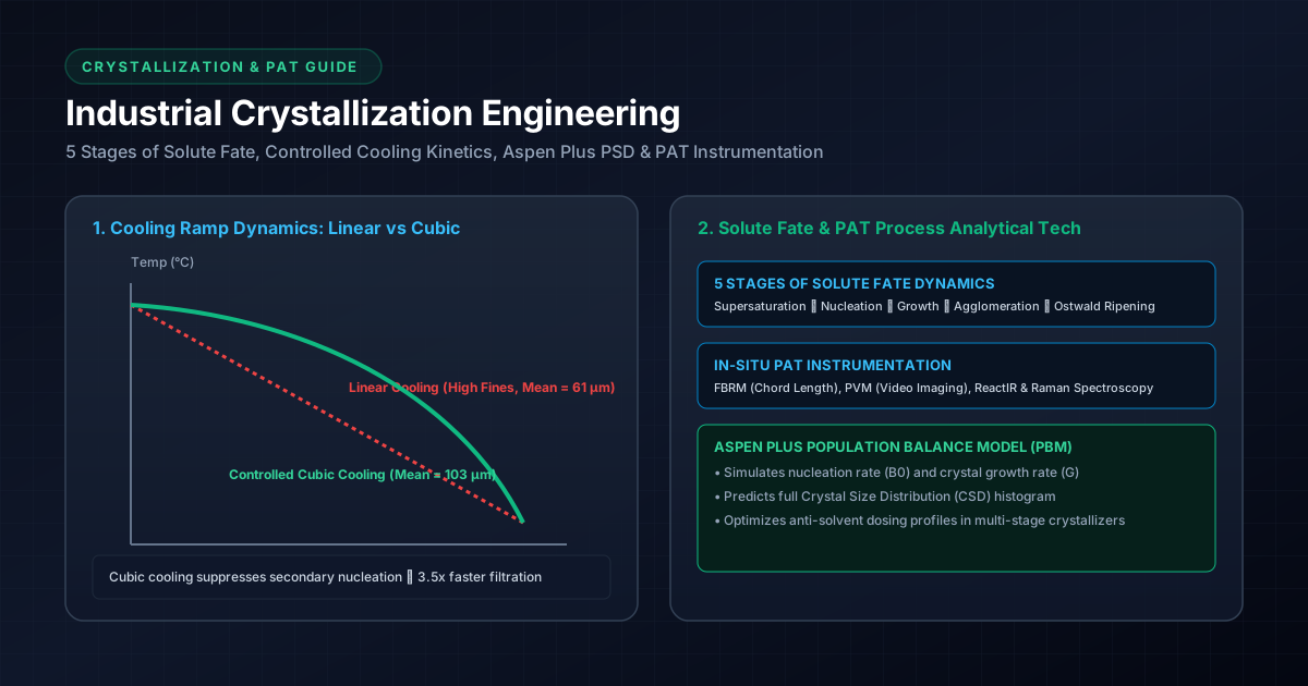
                         COOLING CURVES & METASTABLE ZONE
    Temp (°C)
     100 ┌──────────────────────────────────────────────────────────┐
         │ Fast Shock Cooling (Uncontrolled Nucleation -> Fines)    │
      80 │ ── ── ── ── ── ── ── ── ── ── ── ──                      │
         │                                                        │
      60 │   Linear Cooling                    Controlled Cubic   │
         │                                      Cooling Profile   │
      40 │                                                        │
         │     └──────────────────────────────────┴───────────────  │
      20 └──────────────────────────────────────────────────────────┘
         0                 2                 4                 6  Time (Hours)
- Shock / Fast Cooling:
- Rapid cooling pushes slurry across the Metastable Zone Limit ().
- Explosive primary nucleation occurs. Produces ultra-fine crystals (), broad bimodal PSD, severe impurity entrapment, and heavy cold-wall scaling.
- Linear Cooling ():
- High cooling rate at early batch stages when crystal surface area is small. Generates excessive early supersaturation, triggering unwanted secondary nucleation.
- Controlled Cubic Cooling ():
- Slow initial cooling rate when crystal surface area is small, accelerating as total crystal surface area grows.
- Result: Keeps supersaturation strictly constant within the MSZW window, maximizing growth () while suppressing nucleation (). Produces large, uniform crystals () with narrow Span ().
# 3.2 Agitation & Shear Energy Mechanics
Agitation balances mass transfer (liquid-side boundary layer diffusion) against physical crystal attrition:
Where is liquid film boundary layer thickness, is solute diffusivity, and is mass transfer coefficient.
- Low Agitation (Tip Speed ):
- Thick boundary layer ( large). Growth is mass-transfer limited.
- Settling of crystals occurs at reactor bottom; non-uniform suspension leads to localized supersaturation spikes.
- Optimal Agitation (Tip Speed ):
- Thin boundary layer ( small). Growth becomes surface-integration limited.
- Homogeneous crystal suspension ( - Just Suspended Speed achieved per Zwietering equation).
- Excessive High Agitation (Tip Speed ):
- Severe mechanical collision between impeller blades and crystals.
- Mechanical Attrition & Secondary Nucleation: Large crystals shatter; secondary nucleation rate scales as . Fines content skyrockets ( drops sharply).
# 4. Aspen Plus Simulation & Manual Kinetics Hand Calculation
# 4.1 Population Balance Equation (PBE) Formulation
For a continuous mixed-suspension, mixed-product removal (MSMPR) crystallizer at steady state:
Where:
- is population density ().
- is characteristic crystal length (m).
- is crystal growth rate (m/s).
- is mean residence time (s).
Analytical solution for size-independent growth:
Where is nuclei population density, and is total nucleation rate.
# 4.2 Power-Law Kinetic Rate Equations
Aspen Plus utilizes Power-Law expressions for Nucleation () and Growth ():
Where is total suspension density (), is absolute supersaturation, are kinetic rate constants, and are kinetic exponents.
# 4.3 Aspen Plus Simulation Case Study
# Problem Statement:
Simulate a continuous MSMPR Cooling Crystallizer producing Paracetamol from an aqueous feed stream ( Paracetamol at ).
- Feed Flow Rate: .
- Operating Temperature: .
- Slurry Volume (): .
# Kinetic Parameters Input to Aspen `Cryst` Block:
- Nucleation Constant (): .
- Nucleation Supersaturation Exponent (): .
- Suspension Density Exponent (): .
- Growth Constant (): .
- Growth Exponent (): .
- Crystal Density (): .
# Aspen Simulation Execution Procedure:
- Select Property Method: NRTL (Non-Random Two-Liquid) for liquid phase activity coefficients.
- Define Component System:
PARACETAMOLandWATER. - Add
CrystBlock: ConnectFEEDstream and separateSOLIDS&LIQUIDoutput streams. - Set Crystallizer Specs: Temperature = , Pressure = , Volume = .
- Configure Particle Size Grid (Substream
MIXED/ PSD Mesh): Define 20 size intervals from to . - Input Kinetic Coefficients () in the
Cryst -> Kineticstab. - Run Simulation (
F5).
# Aspen Simulation Results Output:
# 1. Mass Balance & Yield:
- Feed Solute Flow: Paracetamol.
- Equilibrium Solubility at (): ( un-crystallized in mother liquor).
- Crystallized API Yield: ( recovery).
- Suspension Density (): .
# 2. Residence Time & Growth Kinetics:
- Slurry Flow Rate (): .
- Mean Residence Time (): .
- Calculated Supersaturation (): .
- Calculated Growth Rate (): .
- Calculated Nucleation Rate (): .
# 3. Moments of Distribution & Predicted PSD Percentiles:
- Moment 0 ( - Total Number): .
- Moment 1 ( - Total Length): .
- Moment 2 ( - Total Area): .
- Moment 3 ( - Total Volume): .
# Aspen Output Particle Size Percentiles:
# 4.4 Manual Kinetics & Mass Balance Hand Calculation Case Study: Impact of Cooling Ramp Rate on Expected Crystal Size () & Yield
To complement software simulations, process engineers perform manual hand calculations using kinetic rate expressions and moment balances to predict average crystal size under different cooling ramps.
# Plant Batch Scenario Data:
A () MSGL jacketed reactor undergoes batch crystallization:
- Initial Solute Charge: solute dissolved at ().
- Final Target Temperature: where equilibrium solubility .
- Crystal Density (): .
- Volumetric Shape Factor (): (spherical/cubical approximation ).
- Seed Loading: ( seed) charged at with uniform seed size .
- Kinetic Rate Parameters:
- Growth Rate:
- Nucleation Rate:
# Step 1: Calculate Theoretical Batch Yield ()
# Step 2: Compare Linear Cooling vs. Controlled Cubic Cooling Ramps
# Case A: Fast Uncontrolled Linear Cooling ( in , Ramp )
Because the initial temperature drop is rapid when total crystal surface area is small, supersaturation spikes to a high level: .
- Calculate Nucleation Rate ():
- Calculate Total Nuclei Born in ():
- Calculate Seed Particle Count ():
- Calculate Total Particle Count ():
- Calculate Expected Average Particle Mass & Mean Size ():
# Case B: Controlled Cubic Cooling Ramp ( over )
Using the cubic ramp , supersaturation is maintained strictly low and constant: .
- Calculate Nucleation Rate ():
- Calculate Total Nuclei Born in ():
- Calculate Total Particle Count ():
- Calculate Expected Average Particle Mass & Mean Size ():
# Hand Calculation Results Comparison Matrix
| Cooling Operating Mode | Total Cooling Duration | Average Supersaturation () | Total Particle Count () | Nucleated Fines Fraction | Predicted Mean Size () | Filterability Impact |
|---|---|---|---|---|---|---|
| Fast Linear Cooling | (High Spikes) | Fines | Slow ANFD filtration rate; high cake resistance | |||
| Controlled Cubic Ramp | (Low Constant) | Fines | Faster filtration rate; clean washing |
# 5. Analytical Instrumentation for In-Line & Off-Line Crystallization Monitoring
Modern Quality by Design (QbD) relies on Process Analytical Technology (PAT) probes installed directly inside the crystallizer for real-time feedback control:
                        PAT REAL-TIME CRYSTALLIZATION MONITORING
 ┌─────────────────────────────────────────────────────────────────────────────┐
 │ Reactor Vessel                                                              │
 │   ┌─────────────┐     ┌─────────────┐     ┌─────────────┐     ┌───────────┐ │
 │   │ FBRM Probe  │     │ PVM Camera  │     │ ATR-FTIR    │     │ Raman     │ │
 │   │ (Chord      │     │ (Real-Time  │     │ Probe       │     │ Probe     │ │
 │   │  Length)    │     │  Microscopy)│     │(Supersatn)  │     │(Polymorph)│ │
 │   └──────┬──────┘     └──────┬──────┘     └──────┬──────┘     └─────┬─────┘ │
 └──────────┼───────────────────┼───────────────────┼──────────────────┼───────┘
            ▼                   ▼                   ▼                  ▼
 ┌─────────────────────────────────────────────────────────────────────────────┐
 │ Automated Closed-Loop Control System (Dynamic Heating/Cooling Control)      │
 └─────────────────────────────────────────────────────────────────────────────┘
# 5.1 In-Line Real-Time PAT Probes
# 1. Focused Beam Reflectance Measurement (FBRM)
- Principle: A laser beam rotates at high speed () through a sapphire window probe into the slurry. As the laser scans across a crystal, it measures the backscattered light duration, converting it into a Chord Length Distribution (CLD).
- Application: Tracks real-time particle counts per second () to detect exact onset of Primary Nucleation (MSZW boundary), secondary nucleation, agglomeration, and dissolution during heating cycles.
# 2. Process Video Microscopy (PVM) / In-Situ Imaging
- Principle: High-resolution optical camera probe with illuminated stroboscopic LED lighting takes real-time high-magnification images ( to ) of crystals suspended in mother liquor.
- Application: Provides visual verification of crystal habit/aspect ratio (needles, plates, cubes) and detects severe agglomeration or liquid-liquid phase separation (LLPS / oiling out).
# 3. Attenuated Total Reflectance FTIR (ATR-FTIR)
- Principle: Measures infrared absorption spectrum of the liquid mother liquor via a diamond ATR tip. Solute-specific absorption peaks calibrate directly to liquid solute concentration ().
- Application: Calculates real-time supersaturation () independently of suspended solid crystal concentration.
# 4. In-Situ Raman Spectroscopy
- Principle: Measures inelastic laser scattering corresponding to molecular vibrational modes of solid crystal lattices.
- Application: Monitors Polymorphic Form Transformation in real time (e.g. tracking conversion of metastable Form II to stable Form I inside the slurry).
# 5.2 Off-Line Quality Control (QC) Instruments
# 1. Laser Diffraction Particle Size Analyzer (e.g. Malvern Mastersizer 3000)
- Principle: Measures angular light scattering intensity when powder (wet dispersion or dry powder feeder) passes through a Helium-Neon laser beam (Mie Theory / Fraunhofer Approximation per ISO 13320).
- Application: Standard QC release testing for , and Span.
# 2. Powder X-Ray Diffraction (PXRD)
- Principle: X-ray beam strikes powder sample at varying Bragg angles (). Diffracted peaks provide unique fingerprint of crystal unit cell dimensions.
- Application: Confirms 100% polymorphic purity and quantifies amorphous content.
# 3. Differential Scanning Calorimetry (DSC) & TGA
- Principle: Measures heat flow and weight loss as sample is heated at .
- Application: Identifies melting point (), enthalpy of fusion (), solvates, hydrates, and decomposition temperature.
# 6. Summary Table of Governing Crystallization Equations
| Engineering Parameter | Symbol / Variable | Governing Mathematical Equation | Physical Meaning |
|---|---|---|---|
| Supersaturation Ratio | Thermodynamic driving force for crystallization | ||
| Critical Nucleus Radius | Minimum stable nucleus radius | ||
| Nucleation Free Energy | Energy activation barrier for primary nucleation | ||
| Cubic Cooling Curve | Constant supersaturation cooling profile | ||
| Agitator Tip Speed | Shear stress metric for mechanical attrition | ||
| Population Balance (PBE) | Particle count density across size classes | ||
| Aspen Growth Rate | Crystal linear growth velocity (m/s) | ||
| Aspen Nucleation Rate | Nuclei birth rate (nuclei / m s) | ||
| Distribution Moment 3 | Proportional to total crystal volume/mass |
# 7. Governing Regulatory & Quality Guidelines
- ICH Q6A: Test Procedures and Acceptance Criteria for New Drug Substances and Products: Chemical Substances (Polymorphism & PSD Specs).
- ICH Q8 (R2): Pharmaceutical Development: Quality by Design (QbD) Design Space for Crystallization Process Parameters.
- ISO 13320:2020: Particle Size Analysis — Laser Diffraction Methods.
- FDA cGMP 21 CFR Part 211.110: Sampling and testing of in-process materials and drug products.