# How to Design a Cleanroom AHU System for Pharmaceutical Facilities: ISO 5, 6, 7, 8 & EU GMP Grade A, B, C, D Standards
# Executive Summary & cGMP HVAC Context
In pharmaceutical API manufacturing, sterile injectable compounding, solid oral dosage (SOD) processing, and biopharmaceutical facilities, the Air Handling Unit (AHU) and HVAC system is a critical cGMP utility. Unlike commercial HVAC systems that only manage occupant thermal comfort, a pharmaceutical cleanroom AHU serves four primary regulatory safety functions:
- Airborne Contamination Control: Removing non-viable particulates and viable microorganisms via multi-stage HEPA filtration.
- Cross-Contamination Prevention: Maintaining positive or negative differential pressure cascades () between cleanroom zones to prevent cross-contamination between different drug products.
- Environmental Parameter Control: Regulating room temperature () and relative humidity () to prevent static electricity, powder agglomeration, and microbial proliferation.
- Air Change & Dilution Rates: Providing specified Air Change Rates per Hour (ACH) to rapidly flush out contaminants during static and operational states.
This comprehensive technical guide provides chemical and pharmaceutical process engineers, HVAC designers, and validation managers with an authoritative design framework, a regulatory mapping matrix, and a worked step-by-step engineering calculation for a Grade C / Class 100,000 (1 Lakh) Cleanroom AHU System.
# 1. cGMP & ISO Cleanroom Standards Mapping Matrix
Pharmaceutical cleanroom classification is governed internationally by EU GMP Annex 1, ISO 14644-1, and US FED STD 209E. The table below establishes the direct equivalence, airborne particle limits, and target Air Change Rates per Hour (ACH):
| EU GMP Cleanroom Grade | ISO 14644-1 Equivalent Class | US FED STD 209E Class | Max Particles (At Rest) | Max Particles (In Operation) | Target Air Change Rate (ACH) / Velocity | Primary Pharma Application |
|---|---|---|---|---|---|---|
| Grade A | ISO 5 | Class 100 | Laminar Flow () | Aseptic filling, stopper bowl, open ampoule filling | ||
| Grade B | ISO 5 (Rest) / ISO 7 (Ops) | Class 100 / Class 10,000 | 40 – 60 ACH | Background environment for Grade A aseptic filling | ||
| Grade C | ISO 7 (Rest) / ISO 8 (Ops) | Class 10,000 / Class 100,000 (1 Lakh) | 20 – 40 ACH (30 Design Standard) | API formulation, tablet compression, solution prep | ||
| Grade D | ISO 8 (Rest) / Unclassified | Class 100,000 (1 Lakh) / Unclassified | Not Defined | 10 – 20 ACH | Primary packaging, component washing, equipment storage |
# 2. Sensible Load, Latent Load & Sensible Heat Ratio (SHR) in Cleanroom Psychrometrics
The thermal and dehumidification performance of a pharmaceutical AHU is governed by the relationship between Sensible Heat Load (), Latent Heat Load (), and the Sensible Heat Ratio (SHR):
# 2.1 Sensible Heat Load ()
Sensible heat load represents the thermal energy added to or removed from the cleanroom that changes the dry-bulb temperature () without altering the moisture content (humidity ratio ):
Primary Sources of Sensible Heat in Pharma Cleanrooms:
- Equipment motors, reactors, fluid bed dryers, autoclaves, and tablet presses ().
- Cleanroom lighting fixtures ().
- Building envelope conduction (roof, walls, double-glazed viewing panels).
- Fan motor heat gain ( temperature rise across AHU supply fan).
- Operator sensible body heat emission ().
# 2.2 Latent Heat Load ()
Latent heat load represents the thermal energy associated with the addition or removal of moisture (water vapor) at constant dry-bulb temperature, causing a change in humidity ratio ():
(where is the humidity ratio in or , and is the latent heat of vaporization of water).
Primary Sources of Latent Heat in Pharma Cleanrooms:
- Outdoor fresh air intake moisture load (hot & humid ambient summer air).
- Operator respiration and perspiration ( moisture per operator).
- Open aqueous processing tanks, CIP washdown water evaporation, and steam leaks.
# 2.3 Sensible Heat Ratio (SHR) & Its Critical Importance
The Sensible Heat Ratio (SHR) is the fraction of total cooling load attributable to sensible heat transfer:
                          PSYCHROMETRIC SHR LINE ON CHART
  Humidity Ratio (W)
    ▲
    │                                          ● Outdoor Air (40°C DB, 28°C WB)
    │                                         /
    │                                        /
    │       ● Cleanroom State (20°C, 45% RH)/
    │      /│                           /
    │     / │                          /
    │    /  │ <--- Low SHR Slope      /
    │   /   │                        /
    │  ●────┴───────────────────────┘
    │ Apparatus Dew Point (ADP = 8.5°C)
    └──────────────────────────────────────────────► Dry-Bulb Temp (°C)
# Why SHR is Crucial in Pharmaceutical AHU Design:
- Determines Supply Air State Point & Psychrometric Slope:
On a psychrometric chart, the SHR value defines the exact slope of the condition line connecting the supply air state point to the cleanroom design point (). A lower SHR (high latent moisture load) results in a steeper slope. - Dictates Apparatus Dew Point (ADP) & Deep Cooling Requirements:
When an AHU handles high latent loads (), the cooling coil must chill the air down to a low Apparatus Dew Point (ADP = ) to condense out moisture. This chills the supply air below the required dry-bulb room entry temperature. - Mandates Reheat Thermal Duty:
Because air leaving the cooling coil at ADP is cold () and saturated (), passing this air directly into the cleanroom would cause severe room over-cooling. A Reheat Coil (hot water or electric) is mandatory to raise the air temperature to , dropping its relative humidity to the target before entering the cleanroom. - Governs Coil Bypass Factor ():
Pharma cleanroom AHUs require deep 6-row or 8-row cooling coils with low bypass factors () to ensure all air makes contact with fins for maximum moisture condensation.
# 3. Multi-Stage Air Handling Unit (AHU) Architecture
A cGMP-compliant pharmaceutical AHU consists of a rigid double-skin insulated casing ( polyurethane foam [PUF] or rockwool) with a thermal break framework to prevent condensation and thermal bridging.
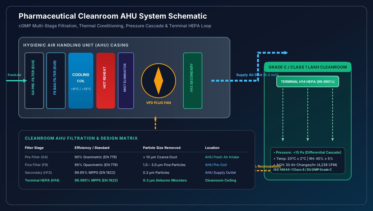
Interactive Engineering Tool: Perform psychrometric air calculations, size cooling coils, determine CFM, and calculate duct pressure drops using our interactive AHU Design & Psychrometric Calculator.
# 4. Cross-Contamination & Differential Pressure Cascade Control
Cross-contamination between adjacent manufacturing bays is prevented by establishing a Differential Pressure Cascade ():
+-------------------------------------------------------------------------+
|                  DIFFERENTIAL PRESSURE CASCADE ARCHITECTURE             |
+-------------------------------------------------------------------------+
|  GRADE C CLEANROOM        --->  AIRLOCK (PAL / MAL)  --->  UNCLASSIFIED   |
|  [Pressure: +15 Pa]              [Pressure: +10 Pa]        [Pressure: 0 Pa] |
|                                                                         |
|  * Air flows OUTWARD from cleanest zone to less clean zone.              |
|  * Differential Pressure (ΔP >= 10 to 15 Pa) maintained via BMS damper. |
+-------------------------------------------------------------------------+
# 5. Environmental Monitoring & cGMP Compliance
Continuous validation and monitoring of environmental parameters ensure cleanrooms remain within validated state:
- Non-Viable Airborne Particle Monitoring: Laser particle counters measuring and counts via isokinetic sampling heads.
- Viable Microbial Environmental Monitoring: Active Air Samplers ( TSA impaction), Settle Plates ( TSA), and Contact Plates ( Rodac).
- Environmental Parameter Limits:
- Temperature: (Operator perspiration & comfort control).
- Relative Humidity: (Prevents static powder charge at and microbial growth at ).
- Airflow Velocity: Grade A Unidirectional Flow ().
# 6. Worked Step-by-Step Cleanroom AHU Sizing Illustration
# Problem Statement:
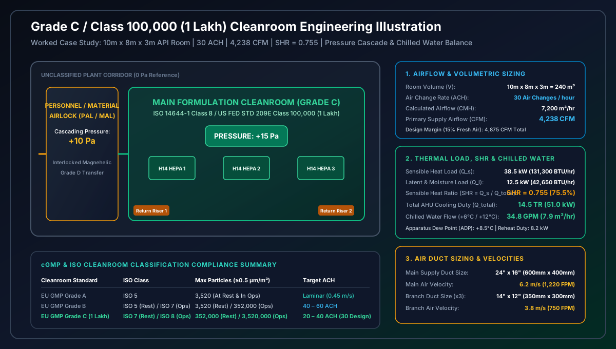
Design a cleanroom AHU system for a Grade C / Class 100,000 (1 Lakh) API Powder Formulation Room in an Indian pharmaceutical plant.
# Given Design Parameters:
- Cleanroom Dimensions: Length , Width , Height .
- Target Cleanroom Class: EU GMP Grade C / ISO 14644-1 Class 8 / US FED STD 209E Class 100,000 (1 Lakh).
- Target Air Change Rate (ACH): .
- Outdoor Design Conditions: (Hot & Humid Summer).
- Inside Design Conditions: (Dew Point ).
- Chilled Water Supply / Return: ().
- Occupancy: 4 Operators ( sensible / latent per person).
- Equipment Heat Load: Motors/Sensors.
# Step 1: Cleanroom Volume & Primary Airflow Rate Calculation
# 1. Calculate Cleanroom Gross Volume ():
# 2. Calculate Required Supply Airflow in Cubic Meters per Hour (CMH):
# 3. Convert Airflow to Cubic Feet per Minute (CFM):
# 4. Add Design Leakage & Fresh Air Intake Margin ():
# Step 2: Psychrometric Thermal Load, Sensible Heat Ratio (SHR) & Chilled Water Calculation
# 1. Total Sensible Heat Load ():
- Envelope Conduction (Walls + Ceiling + Glass)
- Equipment Heat Load
- Lighting Load ()
- Occupants ()
- Fan Heat Gain
# 2. Total Latent & Fresh Air Dehumidification Load ():
- Occupants ()
- Fresh Air Dehumidification Load ()
# 3. Total AHU Cooling Duty ():
Convert kW to Tons of Refrigeration (TR):
# 4. Sensible Heat Ratio (SHR) Calculation:
Psychrometric Analysis: An indicates that of the total cooling capacity is dedicated to sensible temperature reduction and to latent moisture removal. To achieve this, the cooling coil must chill air down to an Apparatus Dew Point (ADP) of , followed by of reheat to supply air into the cleanroom at and .
# 5. Calculate Chilled Water Flow Rate (GPM):
Using the standard hydronic heat transfer formula:
Where and ():
(Adding a fouling margin yields a design water flow rate of ).
# Step 3: Equal Friction Air Duct Sizing Calculation
Ducts are sized using the Equal Friction Method at a pressure drop rate of ():
# 1. Main Supply Air Duct Sizing (Airflow = 4,238 CFM):
- Target Velocity () ().
# 2. Branch Supply Ducts Sizing ( Branches, Airflow = 1,413 CFM each):
# 3. Terminal H14 HEPA Diffusers Sizing ( Terminal Units):
# 7. Summary Design Verification Table
| Design Parameter | Engineered Value | cGMP / ISO Regulatory Requirement | Status / Compliance |
|---|---|---|---|
| Cleanroom Classification | Grade C / Class 1 Lakh | ISO 14644-1 Class 8 (In Operation) | Fully Compliant |
| Gross Room Volume | Design Verified | ||
| Air Change Rate (ACH) | for Grade C | Optimal cGMP Margin | |
| Supply Airflow Rate | Based on 30 ACH | Calculated | |
| Sensible Heat Load () | Equipment, Lighting & Conduction | Calculated | |
| Latent Moisture Load () | Fresh Air & Occupant Perspiration | Calculated | |
| Sensible Heat Ratio (SHR) | Governs ADP & Reheat Duty | Psychrometrically Sized | |
| AHU Cooling Duty | Psychrometric | Sized for Peak Summer | |
| Chilled Water Flow | Supply/Return | Hydronically Balanced | |
| Cleanroom Differential Pressure | vs Adjacent Corridor | Cascade Compliant | |
| Main Supply Duct Size | Velocity | Equal Friction Sized | |
| Terminal HEPA Filters | H14 (99.995% MPPS) | EN 1822 Terminal Filter Standard | ASME BPE Certified |
# Regulatory Standards & Code References
- ISO 14644-1:2015: Cleanrooms and associated controlled environments - Part 1: Classification of air cleanliness by particle concentration.
- ISO 14644-4:2001: Cleanrooms and associated controlled environments - Part 4: Design, construction and start-up.
- EU GMP Annex 1: Manufacture of Sterile Medicinal Products (2022 Revision).
- US FED STD 209E: Airborne Particulate Cleanliness Classes in Cleanrooms and Clean Zones.
- ISPE Baseline Guide Volume 4: Water and Steam Systems / HVAC (3rd Edition).
- ASHRAE Standard 170: Ventilation of Health Care Facilities / Cleanrooms.