# Fundamentals of Mass Balance in Process Engineering: Principles, Examples and Applications in Chemical & API Manufacturing
# Executive Summary & Engineering Scope
In chemical manufacturing, specialty chemical processing, and Active Pharmaceutical Ingredient (API) synthesis, Mass Balance (Material Balance) is the fundamental law of quantitative process engineering. Based on the Law of Conservation of Mass, it dictates that mass can neither be created nor destroyed in a non-nuclear process:
Whether designing a multi-tier API synthesis block, sizing a solvent distillation column, calculating batch yield reconciliation, or auditing environmental emissions, a rigorous mass balance is the foundation for:
- Equipment Sizing: Reactor volumes, filter surface areas, condenser cooling duties, and receiver capacities.
- Process Yield Reconciliation: Identifying physical hold-up losses, unreacted raw materials, and secondary side reactions.
- Environmental & Utility Planning: Estimating volatile organic compound (VOC) emissions, effluent COD/BOD loads, and solvent recovery efficiencies.
- Economic Feasibility: Determining raw material cost contribution per kilogram of API (₹/kg API).
This comprehensive guide presents the theoretical principles, unit operation governing equations, standard engineering practices, and a complete 4-stage numerical case study for a multi-step API synthesis plant, accompanied by a continuous distillation and mixing flowsheet.
# 1. Process Engineering Flowsheet: Distillation & Mixing Mass Balance
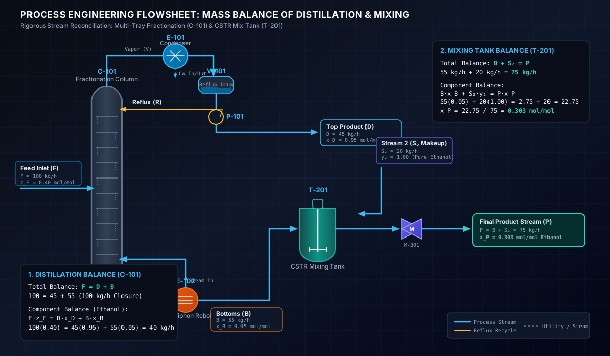
The following engineering flowsheet details a coupled multi-unit operation: a Continuous Multi-Tray Fractionation Column (C-101) with condenser/reflux loop and thermosiphon reboiler, feeding bottoms into a CSTR Mixing Tank (T-201) and inline static mixer:
# Worked Numerical Reconciliation for the Flowsheet:
# Step 1: Overall Distillation Column Balance (C-101)
- Feed (): with Ethanol mole fraction (Ethanol mass flow = ).
- Overhead Product (): High-purity distillate recovering at (Ethanol mass flow = ).
- Bottoms Stream ():
# Step 2: CSTR Mixing Tank Balance (T-201)
- Bottoms Inflow (): ().
- Pure Ethanol Makeup Stream (): ().
- Total Combined Product ():
- Resulting Combined Ethanol Composition ():
# 1. System Boundaries & The General Conservation Law
A System Boundary is a defined physical or conceptual region around a process unit (or an entire plant) across which mass transfers are evaluated:
                  ┌─────────────────────────────────────────┐
                  │            SYSTEM BOUNDARY              │
  Raw Materials   │                                         │   Target Product
  ───────────────►│  [ Reactor / Distillation / Filter ]    ├─────────────────►
  Solvents        │                                         │   Waste / Vent
  ───────────────►│  Accumulation = Input - Output + Gen    ├─────────────────►
                  │                                         │
                  └─────────────────────────────────────────┘
# 1.1 Unsteady-State (Batch) Systems
In batch API manufacturing, conditions change over time (). Energy and mass accumulate inside the vessel:
# 1.2 Steady-State (Continuous) Systems
In continuous operations (such as continuous distillation or microreactors), process variables do not change with time ():
# 2. Unit Operations Mass Balance Governing Equations
Different chemical processing units operate under specialized forms of the general conservation equation:
| Unit Operation | System Type | Primary Input Streams | Primary Output Streams | Governing Mass Balance Equation | Key Engineering Metric |
|---|---|---|---|---|---|
| Batch Synthesis Reactor | Unsteady State | Charge (), Solvent () | Reaction Mass (), Off-gas () | Yield (%), Conversion (%) | |
| Solvent Distillation Column | Steady State | Feed () | Distillate (), Bottoms () | Solvent Recovery Yield (%) | |
| Liquid-Liquid Extractor | Steady State / Batch | Feed (), Extract Solvent () | Extract Phase (), Raffinate Phase () | Partition Coefficient () | |
| Crystallizer & Filter | Batch / Semi-Cont | Slurry Mass (), Wash () | Mother Liquor (), Wet Cake () | Cake Moisture (% w/w) | |
| Vacuum Dryer (ANFD / VTD) | Unsteady State | Wet Cake () | Dry Solid (), Evaporated Vapor () | Residual Solvent (ppm) |
# 3. Reaction Mass Balance: Stoichiometric Principles
In reactive systems, total mass is conserved, but individual chemical species change due to chemical reaction ().
# 3.1 Reaction Conversion ()
Fraction of the key reactant consumed during reaction:
# 3.2 Reaction Selectivity ()
Ratio of desired product formed relative to undesired byproduct :
# 3.3 Isolated Yield ()
Fraction of theoretical maximum product obtained after isolation and drying:
# 4. Comprehensive 4-Stage Industrial API Case Study
To illustrate complete material balance reconciliation, consider a commercial batch manufacturing process producing 1,000 kg of an API Intermediate (Intermediate C) starting from Intermediate A and Reagent B in Toluene solvent.
[ STAGE 1: REACTOR ] ──► [ STAGE 2: EXTRACTION ] ──► [ STAGE 3: FILTRATION ] ──► [ STAGE 4: DRYING ]
  A + B -> C + Byproduct   Biphasic Wash & Separation   Crystallization & ANFD     Vacuum Distillation
# STAGE 1: Batch Reactor Synthesis & Quench
# Process Basis & Charge:
- Intermediate A (MW = 200.0 g/mol): ().
- Reagent B (MW = 150.0 g/mol): (, 10% molar excess).
- Toluene Solvent (): ().
- Catalyst (Homogeneous): .
# Reaction Stoichiometry:
- Reaction Conversion: 96.0% of limiting reagent A converts.
- Moles A converted: .
- Unreacted A remaining: .
- Moles B consumed: .
- Unreacted B remaining: .
- Intermediate C produced: .
- Byproduct D produced: .
# Reaction Quench Charge:
- Process Water for Quench: .
# Stage 1 Material Balance Table:
| Component Tag | Molecular Weight (g/mol) | Charge Mass (kg) | Reaction Output Mass (kg) | Physical State & Stream Assignment |
|---|---|---|---|---|
| Intermediate A | 200.0 | 1,000.0 | 40.0 | Solubilized in Organic Layer |
| Reagent B | 150.0 | 825.0 | 105.0 | Solubilized in Organic Layer |
| Catalyst | — | 25.0 | 25.0 | Dissolved in Aqueous Quench |
| Toluene Solvent | 92.1 | 3,468.0 | 3,468.0 | Organic Layer Solvent |
| Target Intermediate C | 290.0 | 0.0 | 1,392.0 | Main Reaction Product |
| Byproduct D | 60.0 | 0.0 | 288.0 | Dissolved in Aqueous Phase |
| Quench Water | 18.0 | 2,000.0 | 2,000.0 | Aqueous Layer |
| TOTAL MASS | — | 7,318.0 kg | 7,318.0 kg | 100.00% Mass Closure |
# STAGE 2: Biphasic Liquid-Liquid Extraction & Phase Separation
The reaction mass is settled in a separator. The mixture separates into an Upper Organic Layer (Toluene) and a Lower Aqueous Waste Layer.
# Phase Partition Coefficients ():
- Intermediate C: partitions into Toluene organic phase; () lost in aqueous phase.
- Byproduct D & Catalyst: partition into Aqueous waste phase.
- Unreacted A & B: remain in Toluene organic phase.
- Water in Organic Phase: Toluene holds dissolved water ().
# Stage 2 Mass Separation Balance Table:
| Component | Total Input (kg) | Organic Phase Output (kg) | Aqueous Waste Output (kg) | Partition Distribution |
|---|---|---|---|---|
| Intermediate C | 1,392.0 | 1,380.87 | 11.13 | 99.2% Organic / 0.8% Aqueous |
| Intermediate A | 40.0 | 40.0 | 0.0 | 100% Organic |
| Reagent B | 105.0 | 105.0 | 0.0 | 100% Organic |
| Toluene Solvent | 3,468.0 | 3,460.0 | 8.0 | 99.77% Organic |
| Byproduct D | 288.0 | 0.0 | 288.0 | 100% Aqueous Waste |
| Catalyst | 25.0 | 0.0 | 25.0 | 100% Aqueous Waste |
| Water | 2,000.0 | 25.0 | 1,975.0 | 98.75% Aqueous Waste |
| TOTAL PHASE MASS | 7,318.0 kg | 5,010.87 kg | 2,307.13 kg | 100.00% Balance Closure |
# STAGE 3: Crystallization & ANFD Filtration
The organic phase is cooled from to to crystallize Intermediate C.
# Crystallization Parameters:
- Solubility of C in Toluene @ 5°C: ( remains dissolved in mother liquor).
- Crystallized Solid C: .
- ANFD Filtration & Cake Wash: Fresh cold Toluene wash () displacement.
- Wet Cake Moisture: Toluene solvent retention in wet cake.
# Wet Cake Composition:
# Mother Liquor + Wash Filtrate Stream:
- Total Toluene in Filtrate = .
- Dissolved Solid C = .
- Unreacted A & B = .
- Total Filtrate Mass = 3,975.79 kg (Sent to Solvent Recovery Unit).
# STAGE 4: Vacuum Drying & Solvent Recovery
The wet cake is dried in a Vacuum Tray Dryer (VTD) at and .
# Final Drying Balance:
- Evaporated Toluene Vapor: (Condensed in overhead condenser at efficiency = recovered).
- Final Dry Isolated Product C: 1,328.87 kg.
# 5. Overall Plant Mass Balance Reconciliation & Performance Metrics
# Overall Material Balance Summary Table:
| Material Stream Category | Input Mass (kg) | Output Mass (kg) | Mass Balance Percentage |
|---|---|---|---|
| Total Raw Materials (A + B + Cat) | 1,850.0 | — | Primary Reagents Input |
| Total Solvents (Toluene + Water) | 5,968.0 | — | Solvents & Media Input |
| TOTAL PLANT INPUTS | 7,818.0 kg | — | 100.00% Total Charge |
| Isolated Final Product (Dry C) | — | 1,328.87 kg | 16.99% Mass Conversion |
| Recovered Toluene Solvent | — | 3,638.49 kg | 91.70% Solvent Recovery |
| Aqueous Waste Stream | — | 2,307.13 kg | Spent Quench Water |
| Distillation Bottoms & ML Waste | — | 543.51 kg | Mother Liquor Residuals |
| Un-condensed VOC Vent Loss | — | 0.00 kg | Vacuum Condenser Trap |
| TOTAL PLANT OUTPUTS | — | 7,818.00 kg | 100.00% Mass Closure |
# Key Process Performance Indicators (KPIs)
- Overall Isolated Process Yield:
- Process Mass Intensity (PMI):
- Environmental Factor (E-Factor):
# 6. Troubleshooting Mass Balance Discrepancies in Plant Operations
When mass balance closure in an operating plant drops below , process engineers should audit the following common loss mechanisms:
| Diagnostic Symptom | Probable Cause | Corrective Action & Engineering Fix |
|---|---|---|
| Mass Closure < 95% in Distillation | Un-condensed solvent vapor escaping through vacuum pump vent | Install secondary cold brine (-15°C) vent trap trap condenser |
| Low Isolated Product Yield (< 85%) | Crystallization temperature too high; product lost in mother liquor | Lower crystallization temp to 0°C or perform secondary crop ML concentration |
| High Moisture in Wet Cake (> 20%) | ANFD filter cloth blinded or cracked cake channel formation | Implement cake blowdown with warm N2 and mechanical cake smoothing agitator |
| Unaccounted Mass Gain (> 102%) | Inaccurate tank level transmitter calibration or unmetered wash water | Recalibrate load cells and install Coriolis mass flowmeters on feed lines |
# Technical Conclusion
A rigorous mass balance transforms qualitative process chemistry into precise engineering design. By evaluating input streams, reaction stoichiometry, phase equilibrium partitions, and drying kinetics across well-defined system boundaries, process engineers optimize equipment sizing, maximize product yield, and ensure plant environmental compliance.
# Applicable Engineering Standards & Codes Used
The engineering methodologies, design correlations, and safety criteria detailed in this article adhere to the following international standards and industry codes:
- ASME B31.3: Process Piping Code
- API RP 14E: Recommended Practice for Design and Installation of Offshore Production Platform Piping Systems
- Hydraulic Institute Standards (HI 1.3, HI 2.3) for Centrifugal and Positive Displacement Pumps: Hydraulic Institute Standards (HI 1.3, HI 2.3) for Centrifugal and Positive Displacement Pumps
- ISO 5167: Measurement of Fluid Flow by Means of Pressure Differential Devices