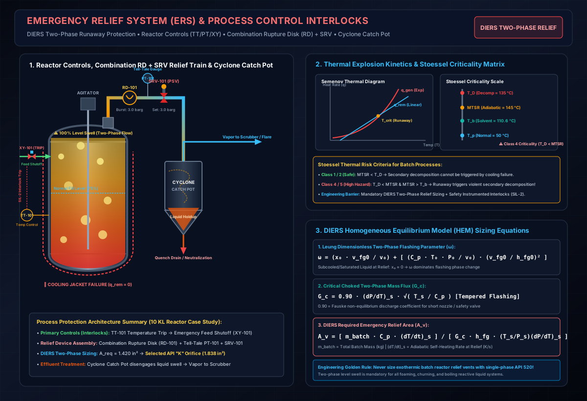
# DIERS Emergency Relief Sizing for Runaway Reactions: Calorimetric Data to Vent Area Calculations (Tempered, Gassy & Hybrid Worked Cases)
# Executive Summary & Industrial Context
In chemical batch reactors, API synthesis vessels, and energetic specialty chemical plants, runaway exothermic reactions present the highest catastrophic risk of vessel overpressurization, catastrophic shell rupture, and toxic/flammable vapor cloud explosions (e.g., Bhopal, Seveso, T2 Laboratories).
When an exothermic reaction loses temperature control due to cooling utility failure, agitator stoppage, or mischarging, the reaction rate accelerates exponentially following Arrhenius kinetics (). Conventional pressure relief valve (PSV) sizing methods per API 520 / ISO 4126 assume single-phase gas or vapor flow. However, during a runaway reaction, rapid boiling and gas evolution cause severe liquid swell (foaming), forcing a two-phase gas-liquid mixture into the relief system.
  WHY CONVENTIONAL SINGLE-PHASE SIZING FAILS IN RUNAWAY REACTIONS
  ┌──────────────────────────────────────────────────────────────────────────┐
  │ ■ Single-Phase Vapor Sizing Assumption: Pure Gas/Vapor Venting           │
  │ ■ DIERS Reality: Two-Phase Liquid Swell (Gas + Entrained Liquid)         │
  │ ■ Volumetric Expansion Ratio: Liquid-gas mixture density is 10x-50x      │
  │   higher than pure vapor, requiring 2x to 10x LARGER VENT AREA!          │
  └──────────────────────────────────────────────────────────────────────────┘
The Design Institute for Emergency Relief Systems (DIERS), established under the American Institute of Chemical Engineers (AIChE), developed the world-standard methodology for sizing emergency relief valves and rupture disks for runaway two-phase flows.
This masterclass chemical engineering guide details:
- Calorimetric Data Requirements (VSP2, ARSST, ARC, RC1).
- Can You Use ARC (Accelerating Rate Calorimetry) Data Alone for DIERS Sizing? (Townsend-Tou -factor correction & limitations).
- System Classification (Tempered, Gassy, and Hybrid systems).
- Hydrodynamic Flow Regimes (Homogeneous Bubbly vs. Churn-Turbulent).
- Validated Mathematical Formulas & Leung / Fauske Sizing Equations.
- 3 Fully Validated Numerical Case Studies (Tempered Nitration, Gassy Diazo Decomposition, and Hybrid Peroxide Oxidation).
- Regulatory Standards & Industry Guidelines (API 521, ISO 4126-10, NFPA 68, OSHA 1910.119 PSM).
# 1. Calorimetric Experimental Data Required for DIERS Sizing
DIERS relief calculations cannot be performed using standard thermodynamic steady-state properties alone. They require adiabatic reaction kinetics and gas/vapor generation rates obtained from specialized low-thermal-inertia calorimetry.
  CALORIMETRIC TEST TRAIN FOR DIERS SIZING
  ┌──────────────────────────────────────────────────────────────────────────┐
  │ 1. DSC / TGA (Differential Scanning Calorimetry): Onset Temp & ΔH (J/g)  │
  │ 2. RC1 (Reaction Calorimetry): Isothermal Heat Flow & Duty q_rxn (W/kg) │
  │ 3. ARSST / VSP2 (Adiabatic Calorimetry): Self-Heating (dT/dt) & dP/dt   │
  └──────────────────────────────────────────────────────────────────────────┘
# Essential Experimental Parameters Required:
# 1. Thermal Mass Inertia (-Factor):
The test cell container absorbs a portion of the reaction heat. The -factor corrects test data to simulate a full-scale plant reactor:
- Low Thermal Inertia Benchmarks: ARSST (), VSP2 (). Plant reactors operate at .
# 2. Self-Heating Rate at Set Relief Pressure :
Extracted from adiabatic vs curve at the temperature corresponding to the relief set pressure (). Expressed in or .
# 3. Maximum Self-Heating Rate :
Peak slope of adiabatic curve, used for un-tempered or worst-case runaway sizing.
# 4. Pressure Rise Rate at Relief Set Pressure :
Rate of pressure rise in or , crucial for Gassy and Hybrid systems.
# 5. Vapor Pressure Slope :
Slope of the saturated vapor pressure curve at relief set pressure, calculated via the Clausius-Clapeyron equation:
# 2. Sizing DIERS Reliefs Using ARC (Accelerating Rate Calorimetry) Data Alone
A common process safety question is: Can process engineers perform DIERS vent sizing using ARC (Accelerating Rate Calorimetry) data alone?
# Short Answer: YES, BUT WITH MANDATORY -FACTOR CORRECTIONS AND FOAMINESS ASSUMPTIONS.
  USING ARC DATA FOR DIERS: THE TWO CRITICAL CHALLENGES
  ┌──────────────────────────────────────────────────────────────────────────┐
  │ 1. HIGH THERMAL INERTIA (φ = 1.5 - 3.0): Metal bomb absorbs 50%-200% of   │
  │    the reaction heat, artificially damping the measured (dT/dt)_ARC rate!│
  │ 2. CLOSED CELL LIMITATION: ARC does not simulate top/bottom blowdown or  │
  │    measure foaminess, requiring a mandatory Homogeneous Flow Assumption.│
  └──────────────────────────────────────────────────────────────────────────┘
# Step-by-Step Methodology to Use ARC Data for DIERS Sizing:
# Step 1: Calculate ARC Cell Thermal Inertia ()
Typical values: Hastelloy bomb (, ) .
# Step 2: Convert Measured ARC Self-Heating Rate to Adiabatic Plant Scale ()
Using the Townsend-Tou / Fisher-Gooch Kinetic Scaling Formula:
Where is the activation energy derived from the linear region of the Arrhenius plot ( vs ).
# Step 3: Flow Regime Assumption (Homogeneous Bubbly Flow)
Because closed ARC spheres cannot observe liquid phase disengagement or foaminess, process engineers must assume Homogeneous Bubbly Flow (). This is conservative and safe.
# Comparison Matrix: ARC vs. VSP2 / ARSST for DIERS Sizing
| Metric / Capability | ARC (Accelerating Rate Calorimetry) | VSP2 (Vent Sizing Package 2) | ARSST (Advanced Reactive System Screening) |
|---|---|---|---|
| Typical -Factor | High () | Low () | Low () |
| -Correction Needed? | Mandatory (High Kinetic Scaling Error if omitted) | Minimal / Optional | Minimal / Optional |
| Direct Vented Blowdown Test? | No (Closed cell only) | Yes (Open cell top/bottom blowdown) | Yes (Open cell venting) |
| Foaminess / Flow Regime Detection | No (Must assume Homogeneous) | Yes (Direct visual/pressure drop test) | Yes (Dip-tube / containment test) |
| Suitability for DIERS Sizing | Possible with -scaling & Kinetic Model | Gold Standard (Direct DIERS Tool) | Excellent (Fast Screening DIERS Tool) |
# 3. Classification of Runaway Reaction Systems
DIERS categorizes runaway reactions into 3 distinct thermodynamic behavior types based on how pressure is generated upon overpressurization:
  ┌──────────────────────────────────────────────────────────────────────────┐
  │                        DIERS SYSTEM CLASSIFICATION                       │
  ├──────────────────────────────────────────────────────────────────────────┤
  │ 1. TEMPERED SYSTEMS (Boiling Solvent Controlled - Evaporative Cooling)  │
  │ 2. GASSY SYSTEMS (Non-Condensable Gas Generation - No Evaporative Cool) │
  │ 3. HYBRID SYSTEMS (Combined Solvent Boiling + Non-Condensable Gas)     │
  └──────────────────────────────────────────────────────────────────────────┘
# Type 1: Tempered Systems (Vapor Pressure / Boiling Controlled)
- Mechanism: System pressure is dictated by the saturated vapor pressure of a volatile solvent (e.g., Toluene, Methanol, DCM, Water).
- Behavior upon Relief: Opening the relief device lowers reactor pressure, causing the solvent to boil vigorously. The latent heat of vaporization () removes reaction heat via evaporative cooling, halting temperature rise at the relief set pressure.
- Key Advantage: Self-limiting peak pressure.
- Sizing Focus: Vent area must be sized to remove heat faster than the chemical reaction generates it.
# Type 2: Gassy Systems (Non-Condensable Gas Generation)
- Mechanism: Pressure rise is caused purely by non-condensable permanent gas generation (e.g., from diazo/azide decomposition, from decarboxylation, from peroxide breakdown).
- Behavior upon Relief: Opening the relief device releases gas, but NO evaporative cooling occurs. The chemical reaction continues to self-heat unabated!
- Key Danger: Pressure continues to rise if the vent area is undersized for peak gas generation.
- Sizing Focus: Vent area must accommodate maximum volumetric gas generation rate at maximum runaway temperature.
# Type 3: Hybrid Systems (Combined Gas Generation & Vapor Pressure)
- Mechanism: Pressure is generated simultaneously by volatile solvent boiling AND non-condensable gas generation (e.g., Nitration in organic solvent generating gases + Toluene vapor).
- Behavior upon Relief: Partial evaporative cooling occurs, but non-condensable gas suppresses vapor condensation in vent headers.
- Sizing Focus: Sized using combined Leung-Fauske hybrid equations.
# 4. Two-Phase Hydrodynamic Flow Regimes & Drift-Flux Parameter ()
When a relief valve opens, two-phase flow enters the vent line. DIERS evaluates vessel hydrodynamics to determine the liquid fraction in the vent stream:
  VESSEL HYDRODYNAMIC FLOW REGIMES IN DIERS

  Homogeneous Bubbly Flow (Worst Case):
  [Gas Bubbles Uniformly Dispersed in Liquid] ──► High Liquid Carryover ──► Maximum Vent Area Required

  Churn-Turbulent Flow (Heterogeneous - Favorable):
  [Large Gas Slugs Break Free from Liquid Phase] ──► Vapor Disengages ──► Reduced Vent Area Required
# 4.1 Drift-Flux Parameter () Formula & Variables
The characteristic terminal rise velocity () of vapor/gas bubbles rising through a liquid pool under gravity is defined by Harmathy's drift-flux equation:
# Term-by-Term Variable Breakdown:
| Symbol | Parameter Description | Standard SI Units | Typical Process Safety Values |
|---|---|---|---|
| Terminal Bubble Rise Velocity | |||
| Liquid Surface Tension | (or ) | (Toluene), (Water) | |
| Gravitational Acceleration | |||
| Saturated Liquid Mass Density | (Organic solvent at ) | ||
| Saturated Vapor Mass Density | (at ) |
# 4.2 Step-by-Step Numerical Worked Calculation of
Worked Example: Calculate for a reactor filled with saturated Toluene at relief set pressure ().
- Step 1: Calculate Buoyancy Term (Numerator):
- Step 2: Divide by Liquid Density Squared (Denominator):
- Step 3: Calculate Fourth Root ( Exponent):
- Step 4: Multiply by Harmathy Constant ():
# 4.3 Flow Regime Selection Criteria & Disengagement Credit
To determine whether liquid phase disengagement occurs, compare vessel superficial gas velocity () to :
- Foaming Liquids (Viscous API Mass / Detergent Surfactants) OR :
- Homogeneous Bubbly Flow dominates. Zero liquid disengagement occurs (), requiring maximum conservative vent area (HEM Model).
- Non-Foaming Liquids AND :
- Churn-Turbulent Flow dominates. Vapor bubbles coalesce into slugs and disengage from liquid pool, reducing required vent area by .
# 5. DIERS Mathematical Formulas & Variable Definitions
# 5.1 Tempered System Vent Sizing Equation (Leung-Fauske Homogeneous Model)
For a tempered system operating under Homogeneous Equilibrium Model (HEM) conditions with a maximum allowable overpressure of above set pressure:
# Term-by-Term Variable Definitions:
| Symbol | Parameter Description | Standard SI Units | Engineering Imperial Units |
|---|---|---|---|
| Required Derated Flow Vent Area | |||
| Total Mass of Reaction Mixture in Vessel | |||
| Specific Heat Capacity of Reaction Liquid | |||
| Adiabatic Self-Heating Rate at Set Pressure | |||
| Latent Heat of Vaporization of Volatile Solvent | |||
| Absolute Relief Set Pressure | |||
| Absolute Saturation Temperature at Set Pressure | |||
| Vapor Pressure Curve Slope at Set Pressure | |||
| Flashing Two-Phase Critical Mass Flux |
# 5.2 Critical Mass Flux () Formulas for Tempered, Gassy & Hybrid Systems
A common source of engineering error is assuming that is identical across all relief scenarios. The critical mass flux depends on nozzle thermophysics:
  CRITICAL MASS FLUX (G_c) FORMULA BREAKDOWN BY SYSTEM TYPE

  1. TEMPERED SYSTEM (Flashing Two-Phase Flow):
     G_c,tempered = 0.90 × (dP/dT)_s × sqrt( T_s / C_p )
     (High Mass Flux: ~2,500 - 5,000 kg/m²·s due to entrained liquid flashing)

  2. GASSY SYSTEM (Non-Condensable Gas Choking):
     G_c,gas = C_d × P_1 × sqrt[ (k M / Z R T_1) × (2 / (k+1))^((k+1)/(k-1)) ]
     (Lower Mass Flux: ~800 - 1,500 kg/m²·s due to low gas phase density)

  3. HYBRID SYSTEM (Combined Boiling + Gas Expansion):
     G_c,hybrid,effective = G_c,tempered / sqrt( 1 + Q_gas / Q_vapor )
     (Intermediate Mass Flux dictated by gas-to-vapor volumetric ratio)
# Detailed Equations by System Type:
- Tempered System Flashing Flux ():
Where is Fauske's non-equilibrium discharge coefficient for flashing two-phase flow through short nozzles and safety valves.
- Gassy System Sonic Gas Flux ():
Where is the isentropic expansion coefficient, is gas molecular weight (), and is gas compressibility factor.
- Hybrid System Effective Flux ():
# 5.3 Gassy System Vent Sizing Equation (Fauske Non-Tempered Model)
For non-tempered gassy systems where pressure rise is driven by non-condensable gas generation:
Where:
- = Maximum volumetric gas generation rate ().
- = Gas density at relief conditions ().
- = Gas-phase critical mass flux ().
# 5.4 Hybrid System Vent Sizing Equation (DIERS Combined Model)
For hybrid systems exhibiting simultaneous solvent boiling and non-condensable gas generation:
# 5.5 Fauske (Omega) Method vs. DIERS Combined / Leung Method: When to Use Which?
A fundamental decision process safety engineers face is selecting between Fauske's Omega () Method and the DIERS Combined / Leung Method:
                    OVERPRESSURE IN CHEMICAL PROCESS VESSEL
                                      │
                   ┌──────────────────┴──────────────────┐
                   ▼                                     ▼
        NON-REACTIVE SYSTEM                     REACTIVE RUNAWAY
   (External Fire, Heat Exchanger         (Nitration, Polymerization,
     Tube Rupture, Pure Flashing)             Decomposition Runaway)
                   │                                     │
                   ▼                                     ▼
       Use Fauske Ω Method                    Use DIERS / Leung
     (API 520 Part I Appendix C)               Combined Method
                   │                                     │
   Calculates two-phase mass flux        Uses calorimetry rates ((dT/dt)_s)
    G_c based on thermodynamic            to size vent for Tempered, Gassy,
          properties alone.                        or Hybrid cases.
# Comparison Matrix: Omega () Method vs. DIERS Combined / Leung Method
| Feature / Metric | Fauske (Omega) Method | DIERS Combined / Leung Method |
|---|---|---|
| Primary Application | Non-reactive two-phase flashing flow (e.g., Fire exposure, physical boiling, valve expansion). | Reactive runaway chemical reactions (e.g., Batch synthesis, nitration, polymerization). |
| Heat & Mass Source | External heat flux () or pressure drop across relief nozzle. | Internal Arrhenius exothermic reaction kinetic rate ( or ). |
| Experimental Data Needed | Standard thermodynamic properties (). | Low-thermal-inertia adiabatic calorimetry data (VSP2, ARSST, ARC). |
| Core Governing Metric | Dimensionless two-phase compressibility parameter . | Adiabatic self-heating rate & gas generation rate . |
| Standard Reference | API 520 Part I (Appendix C), ISO 4126-10. | DIERS Project Manual (AIChE/CCPS), ISO 4126-10. |
# 1. When to Use the Fauske (Omega) Method:
- External Fire Exposure (API 520 Part I Appendix C): Sizing safety relief valves or rupture disks on non-reactive liquid storage tanks, reboilers, or heat exchangers exposed to external pool fire ().
- Physical Flashing without Reaction: Subcooled or saturated liquid venting through safety valves or discharge piping where pressure drop causes immediate boiling (flashing) along the flow path without chemical heat evolution.
- Omega () Parameter Definition:
For a saturated liquid at set pressure ():
# 2. When to Use the DIERS Combined / Leung Method:
- Runaway Exothermic Reactions: Sizing relief vents for chemical synthesis reactors where the reaction rate accelerates exponentially with temperature.
- Calorimetric Testing Available: Sizing based directly on adiabatic calorimeter data (ARSST, VSP2, ARC) measured self-heating rates or gas evolution rates at relief set pressure .
- System Sizing Equations: Sizing across Tempered (latent heat cooling), Gassy (non-condensable gas generation), and Hybrid (combined gas + vapor) system classifications.
# 6. Validated Numerical Case Studies
# Case Study 1: Tempered System (Toluene Nitration in 10 KL GLR Reactor)
# Facility & Chemical Input Parameters:
- Vessel Type: Glass-Lined Reactor ().
- Batch Mass (): (Toluene solvent + nitration mass).
- Relief Set Pressure (): .
- Maximum Allowable Accumulation: overpressure .
- Saturation Temperature (): .
- Calorimetric Self-Heating Rate at Set Pressure : ().
- Liquid Specific Heat (): .
- Latent Heat of Vaporization (): .
- Vapor Pressure Slope : .
  CASE STUDY 1: STEP-BY-STEP CALCULATION VERIFICATION

  Step 1: Calculate Two-Phase Flashing Critical Mass Flux (G_c,tempered)
          G_c,tempered = 0.90 × 8,450 Pa/K × sqrt(431.65 K / 2,200 J/kg·K)
          G_c,tempered = 7,605 × sqrt(0.1962045) = 7,605 × 0.44295 = 3,368.63 kg/m²·s

  Step 2: Calculate Dimensionless Clausius-Clapeyron Group
          [ (T_s / P_s) × (dP/dT)_s ] = (431.65 / 401,300 Pa) × 8,450 Pa/K = 9.089066

  Step 3: Calculate Ideal Required Vent Area (A_ideal)
          Numerator   = m_batch × C_p × (dT/dt)_s = 8,500 kg × 2,200 × 0.45 K/s = 8,415,000 W
          Denominator = G_c × h_fg × [ (T_s/P_s)(dP/dT)_s ] = 3,368.63 × 360,000 × 9.089066 = 11,022,372,216 W/m²
          A_ideal     = 8,415,000 / 11,022,372,216 = 0.00076345 m² = 7.634 cm² = 1.183 in²

  Step 4: Design Required Area with 20% Bubbly Flow Allowance (A_req)
          A_req = 1.183 in² × 1.20 = 1.420 in²
# Selection of Relief Device:
- API 526 Standard Orifice Areas:
- J Orifice Area: (Undersized, as ).
- K Orifice Area: (Adequate margin: ).
- Selected Relief Device: Pressure Safety Valve (PSV) or Rupture Disk with API "K" Orifice.
# Case Study 2: Gassy System (Diazonium Salt Decomposition in 5 KL Reactor)
# Facility & Chemical Input Parameters:
- Vessel Volume: Reactor containing aqueous diazonium salt mass.
- Decomposition Reaction: Generates gas non-condensable at .
- Max Gas Generation Rate from ARSST Calorimetry : at .
- Gas Density (): at relief conditions.
- Gas Critical Mass Flux (): (DIERS ARSST benchmark flow flux).
  CASE STUDY 2: STEP-BY-STEP CALCULATION VERIFICATION

  Step 1: Calculate Volumetric Gas Generation Rate Q_(g, max)
          Q_(g, max) = 3,500 kg × 0.0042 m³/kg·s = 14.70 m³/s

  Step 2: Calculate Gas Mass Flow Rate (m_dot_g)
          m_dot_g = 14.70 m³/s × 2.85 kg/m³ = 41.895 kg/s

  Step 3: Calculate Vent Area (A_req)
          A_req = 41.895 kg/s / 1,250 kg/m²·s = 0.033516 m² = 335.16 cm² = 51.95 in²

  Step 4: Calculate Required Rupture Disk Diameter (D)
          D = sqrt( 4 × 51.95 in² / π ) = 8.13 Inches
- Relief Device Selection: Select Rupture Disk Assembly ().
# Case Study 3: Hybrid System (Organic Peroxide Oxidation)
# Facility & Chemical Input Parameters:
- System pressure generated by both -Butyl hydroperoxide decomposition ( gas) + Acetone solvent boilup.
- Base tempered area , , .
- Base tempered critical mass flux .
  CASE STUDY 3: STEP-BY-STEP CALCULATION VERIFICATION

  Step 1: Calculate Gas-to-Vapor Volumetric Ratio
          Q_gas / Q_vapor = 1.20 / 2.10 = 0.5714

  Step 2: Calculate Hybrid Volumetric Multiplier
          Multiplier = sqrt( 1 + 0.5714 ) = sqrt(1.5714) = 1.25356

  Step 3: Calculate Effective Hybrid Critical Mass Flux (G_c,hybrid)
          G_c,hybrid = G_c,tempered / Multiplier = 3,200 / 1.25356 = 2,552.73 kg/m²·s

  Step 4: Calculate Required Hybrid Vent Area (A_hybrid)
          A_hybrid = 2.45 in² × 1.25356 = 3.071 in²
- API 526 Orifice Selection: Select API "M" Orifice ().
# 7. Interactive DIERS Emergency Relief Vent Sizing Calculator
Perform your own DIERS runaway reaction two-phase relief calculations, Townsend-Tou -scaling, and API 526 orifice sizing online:
👉 Access the Interactive DIERS Emergency Vent Sizing Calculator
  ┌──────────────────────────────────────────────────────────────────────────┐
  │ 💡 ONLINE DIERS SIZING CALCULATOR FEATURES                               │
  ├──────────────────────────────────────────────────────────────────────────┤
  │ ■ Sizing Models: Tempered (Flashing), Gassy (Sonic), & Hybrid Systems   │
  │ ■ Calorimetric Presets: 1-Click loading for Nitration, Diazo, Peroxide   │
  │ ■ Kinetic Scaling: Townsend-Tou ARC φ-factor correction (φ_ARC → 1.0)     │
  │ ■ API 526 Sizing: Automatic nozzle area & orifice designation lookup    │
  └──────────────────────────────────────────────────────────────────────────┘
# 8. Industry Standards & Regulatory References
- AIChE DIERS Project Manual: Emergency Relief System Design Using DIERS Technology (Fisher, H. G. et al., AIChE/DIERS).
- ISO 4126-10: Safety Devices for Protection Against Excessive Pressure — Part 10: Sizing of Safety Valves and Rupture Disks for Gas/Liquid Two-Phase Flow.
- API Standard 520 Part I: Sizing, Selection, and Installation of Pressure-Relieving Devices in Refineries (10th Edition).
- API Standard 521: Pressure-Relieving and Depressuring Systems (7th Edition).
- NFPA 68: Standard on Explosion Protection by Deflagration Venting.
- OSHA 1910.119: Process Safety Management of Highly Hazardous Chemicals (PSM Standard).